DD-5100
supports RFID reader),
GND – ground contact for camera,
CAM – contact to connect video signal cable (wire of camera's video signal needs to be soldered to
soldering area near CAM contact),
CPW – positive power supply contact for camera module – during conversation through this contact
doorphone supplies power to camera.
Table 1: Electric installation wire upon the length
Wire*/length Up to 20 meters Up to 100 meters Up to 200 meters
Handset connection line wire
D=0,5mm / S=0,2mm
2
2 x D=0,5mm / S=0,4mm
2
System power supply wire
S=1mm
2
– –
Electric lock wire
S=0,5mm
2
– –
Door unlock button wire
S=0,5mm
2
– –
*Use a copper wire for installation
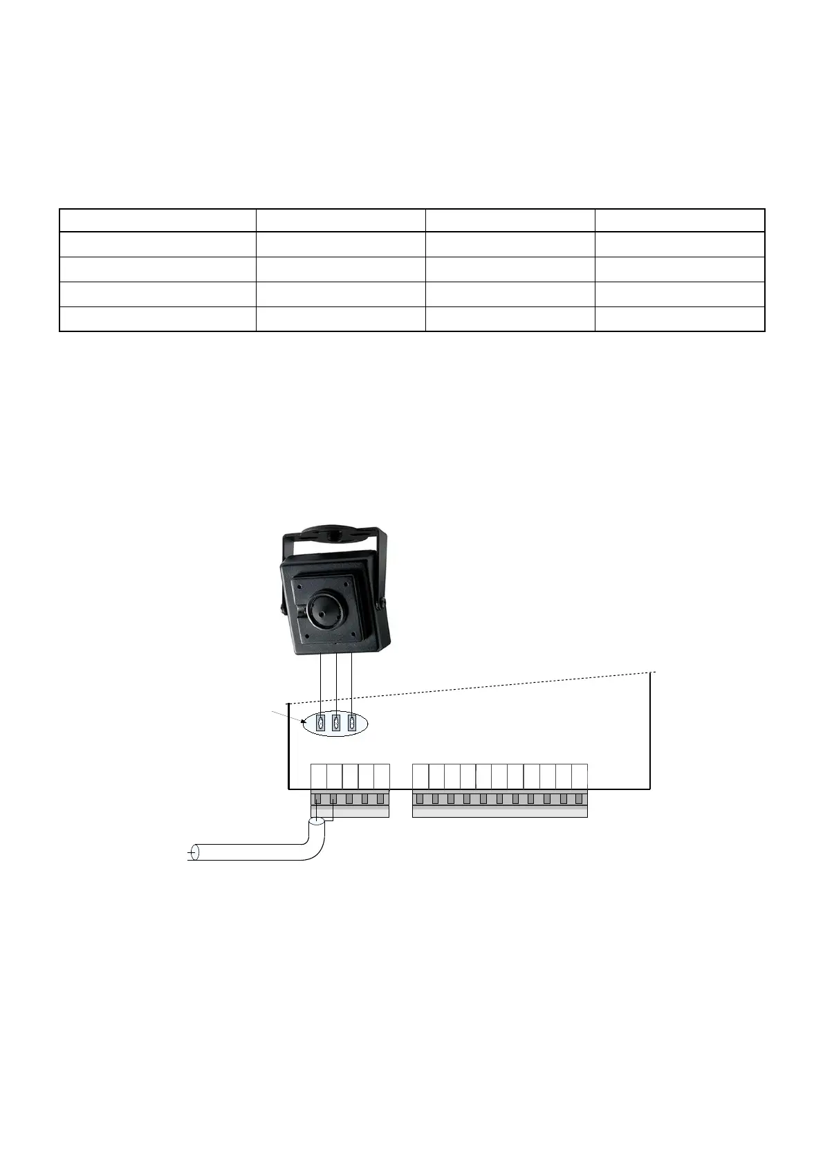
3.2. Video camera wiring diagram
There is a possibility to mount a video camera to a door phone module. See fig. 5 for video camera wiring
diagram. Pay attention, a contact “CAM” is not connected to a door phone circuit, as it is intended for commutation.
GND – ground contact, CPW – video camera power supply contact, 12 V voltage appears when calling and during
conversation session.
In order to ensure quality of image, use a coaxial wire for transfer of video signal.
3.3. Door phone connection to the network
A network connection is needed in case a room (residential house or office) has several entrances. In this
case a door phone module DD-5100 is mounted for each entrance. Several configurations are possible.
If only two doorphones in a network are needed, simplest solution is connect two DD-5100 as shown in fig. 8.
In this configuration one DD-5100 doorphone needs to be configured as L type, and NET1 configuration selected,
other DD-5100 should be configured as H type with NET1 configuration selected. Please refer to Chapter 5
“Doorphone net types and configuration“ for more info.
8
Fig. 5: Video camera wiring diagram