Chapter 3. Connection of DD-5100 door phone
3.1. A standard wiring diagram
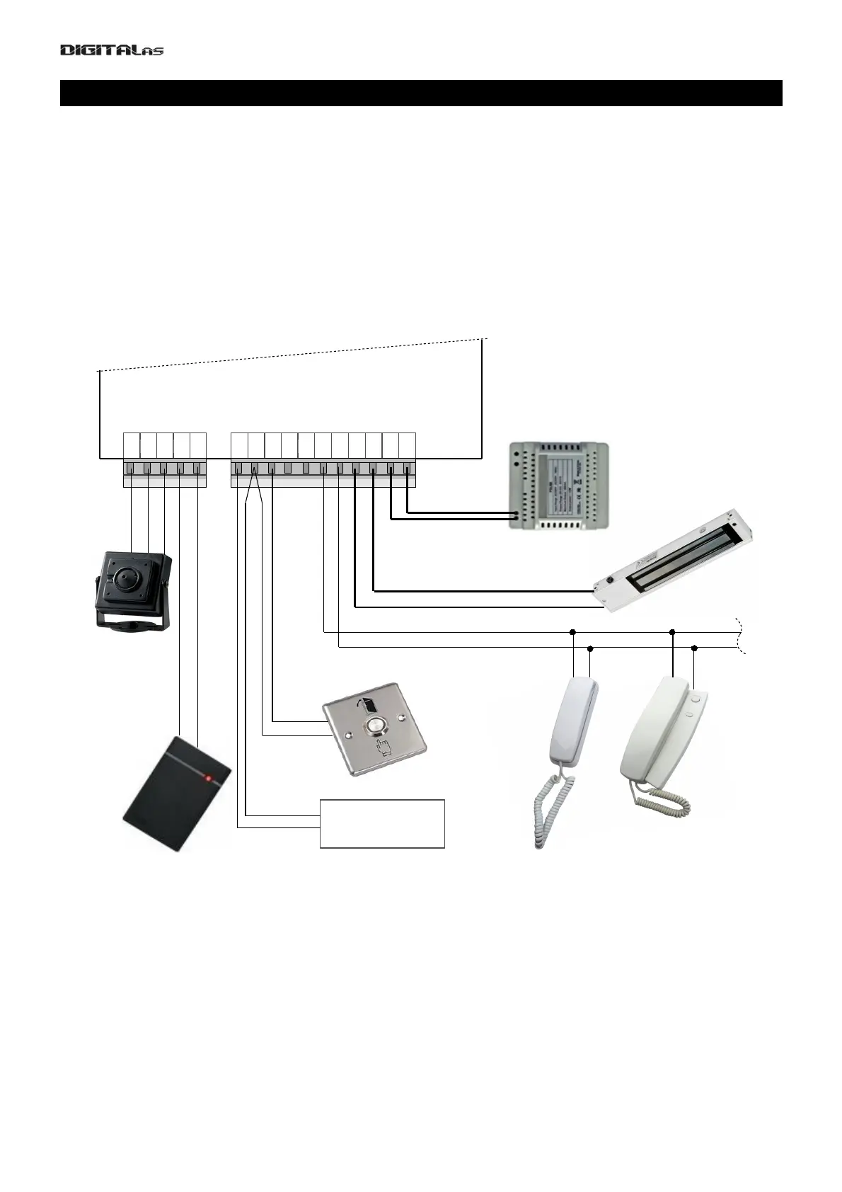
For basic usage of DD5100 doorphone, only connections made to right connector (see Fig. 4) are
mandatory. A minimal standard DD-5100 door phone completion involves:
• Door phone module DD-5100
• Stabilized power supply (12V, 1.5 A)
• Electronic lock
• Door unlock button
• Door phone handsets.
Left connector is dedicated for camera or external RFID reader.
Requirements for wire diameters are given in table 1.
Main contacts (mandatory connections, needed for basic doorphone operation):
GND, LGND – ground contact.
P12V – power supply positive contact,
UNL – contact of inner door opening switch,
LINE – positive line contact (line connects all handsets to doorphone),
LC- – negative contact of electric lock or electromagnet,
LC+ – positive contact of electric lock or electromagnet. By default doorphone drives electromagnet. To
drive electric lock, appropriate settings should be done in doorphone settings menu, please refer to menu section
3.2 on page 18.
Additional contacts (used to implement specific features):
D0, D1 – contacts for „Wiegand“ protocol based RFID reader data lines. RFID reader works only with
special software equipped DD5100 (if during boot R0T0, R1T1 or R1T2 appears on screen, Your DD5100
7
Fig. 4: DD5100 digital doorphone wiring diagram