Do you have a question about the DigiTech QC1938 and is the answer not in the manual?
Steps to inspect the oscilloscope for damage and completeness upon receiving it.
Instructions on adjusting supporting legs and connecting the power cord.
Description and introduction to the front panel controls and features.
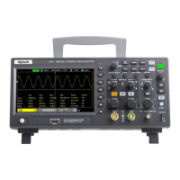
Detailed explanation of the oscilloscope's on-screen display and its elements.
Steps to perform a quick functional check to ensure the oscilloscope is working correctly.
Information about oscilloscope probes, including safety and compensation.
Description of the oscilloscope's menu keys, operation mode keys, and shortcut keys.
Details the various input and output connectors on the oscilloscope's front panel.
Explanation of the multifunctional knob and softkey functions for operation.
Covers Auto Scale, saving, recalling, and default setup procedures.
Details how to adjust the horizontal scale and position of the waveform.
Explains controls for vertical display, scale, position, and input parameters.
Describes how to perform math operations like addition, subtraction, multiplication, division, and FFT.
Explains how to configure the oscilloscope to trigger on specific signal edges.
Details settings for triggering on pulses based on width, polarity, and conditions.
Describes how to trigger based on video signal standards like NTSC and PAL.
Configuration for triggering based on the slope and time of signal transitions.
Sets up triggering when a signal exceeds a specified timeout duration.
Configures triggering based on high and low trigger levels within a waveform amplitude range.
Allows triggering based on specific logic patterns (AND/OR) of channel states.
Triggers based on the time difference between signal edges meeting specific conditions.
Triggers on pulses that cross one threshold but not another.
Sets up triggering for UART serial communication based on start bits, data, or errors.
Configures triggering for LIN bus signals based on frame ID, data, or sync fields.
Sets up triggering for CAN bus communication based on frame types, IDs, and errors.
Configures triggering for SPI bus communication based on data content and timeout.
Sets up triggering for IIC bus signals based on start/stop bits, address, or data.
Instructions for decoding UART serial communication signals.
Instructions for decoding LIN bus communication signals.
Instructions for decoding CAN bus communication signals.
Instructions for decoding SPI serial communication signals.
Instructions for decoding IIC bus communication signals.
Steps for saving and recalling settings and waveforms to internal memory.
Instructions for saving and recalling data to/from external USB storage.
Procedure for saving the current screen display as a picture file.
Operations for creating, deleting, and renaming files and folders on external storage.
Method for taking quick visual measurements using graticule divisions and scale factor.
Detailed guide on using amplitude and time cursors for measurements.
How to perform automatic measurements and display up to four parameters.
Instructions on starting, stopping, and performing single acquisitions.
Steps to upgrade the oscilloscope software using a USB flash drive.
Procedure for optimizing measurement accuracy through self-calibration.
Using the Pass/Fail function to judge input signals against defined rules.
Automatic adjustment of controls to display input signals effectively.
Procedure for recalling the oscilloscope's factory default settings.
How to enter and exit the dual-window display mode for waveform analysis.
Instructions for selecting waveform types and adjusting parameters like frequency and amplitude.
Configuration of amplitude (AM) and frequency (FM) modulation for waveforms.
Setting up burst output for waveforms, including the number of cycles.
Procedure for downloading and installing the necessary IO driver software.
| Brand | DigiTech |
|---|---|
| Model | QC1938 |
| Category | Test Equipment |
| Language | English |