11
Important: The limit switch acts closing, never let that the door stop crashing with the
mechanic limit (for example a wall or a metallic column). Let allways a space between
this and the door. Check that this occur too when the door is moving automatically. If
not, move the magnet to forward in order to the motor stops the door before (take the
inertia of the door account).
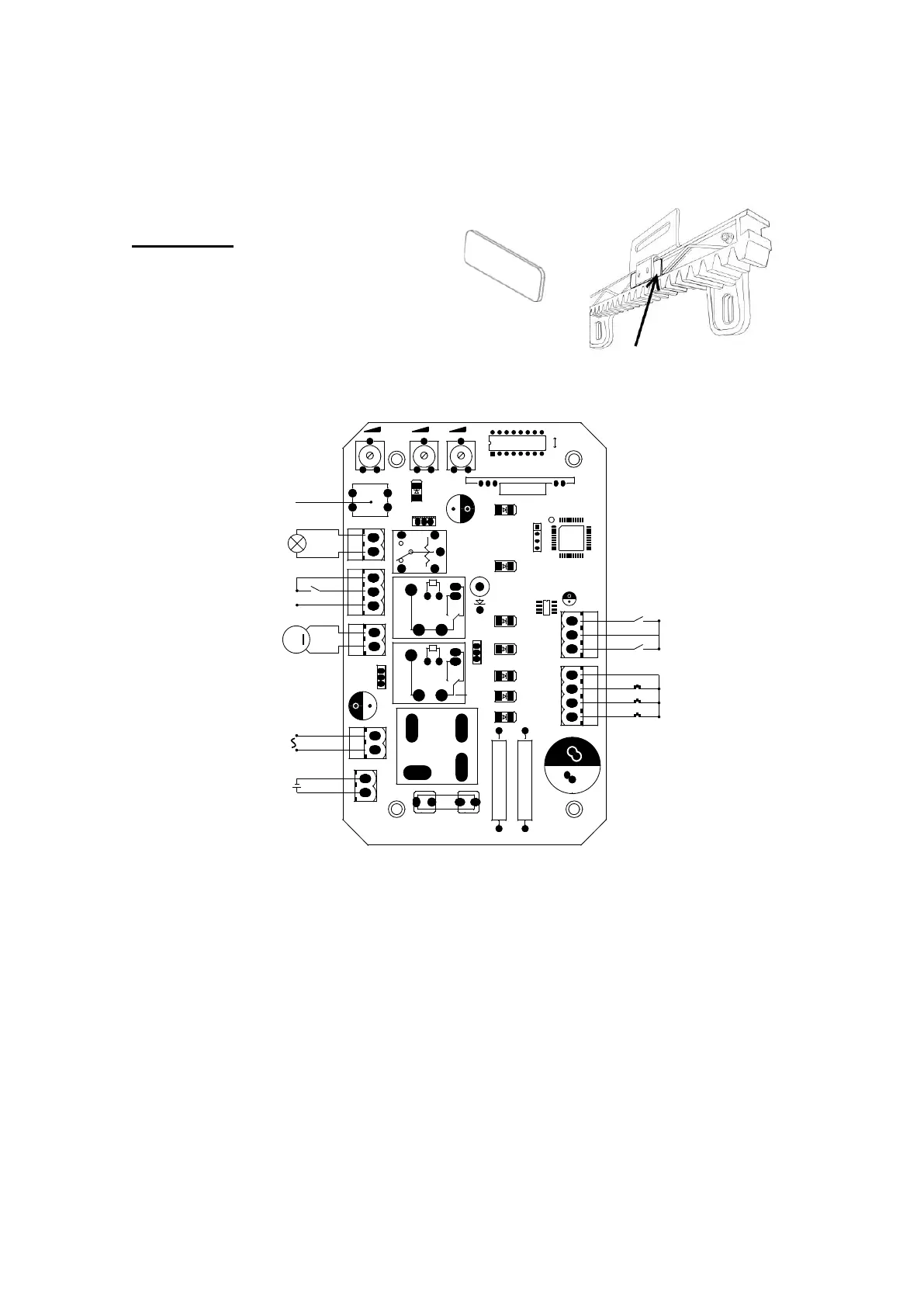
Spacer plate
Place the piece between the limit
switch bracket and the rack as shown
in the image.
3.3.5 Control board wiring
VR1VR1 VR2VR2 VR3VR3
U1U1
ONON
OFFOFF
J9J9
LRNLRN
K4K4
UV2UV2
J8J8
RL6RL6
J1J1
J4J4
UV4UV4
C3C3
J2J2
BAT+BAT+
F1F1
D6D6
DKC500DC.PCBDKC500DC.PCB
2015.01.052015.01.05
R8R8 R9R9
N1N1
RL1RL1
RL2RL2
D15D15
C20C20
PWRPWR
SW1SW1
U4U4
U3U3
C2C2
J10J10
J7J7
C23C23
+ALM-+ALM-
5
6
7
MOTMOT
POWERPOWER
1
2
3
5
7
9
OPOP
COMCOM
CLCL
4
3
2
1
M
24VAC24VAC
24VDC24VDC
LearningLearning buttonbutton
OPOP
CLCL
COMCOM
COMCOM
AlarmAlarm lamplamp
StopStop buttonbutton
CloseClose buttonbutton
OpenOpen buttonbutton
COMCOM
24VDC24VDC motormotor
InfraredInfrared sensorsensor
StorageStorage batterybattery
Figure 10
The control board have some LEDS to indicate the outputs state to find easily
troubles: El cuadro de maniobras está dotado con una serie de leds (luces) que
indican el estado de las entradas para encontrar más fácilmente eventuales
anomalías de instalación:
LED nº 1: open button Normally Open
LED nº 2: close button Normally Open
LED nº 3: stop button Normally Open
LED nº 5: low limit switch (right) Normally Close
LED nº 7: high limit swich (left) Normally Close