Millbrook House, Grange Drive, Hedge End, Southampton, SO30 2DF
27
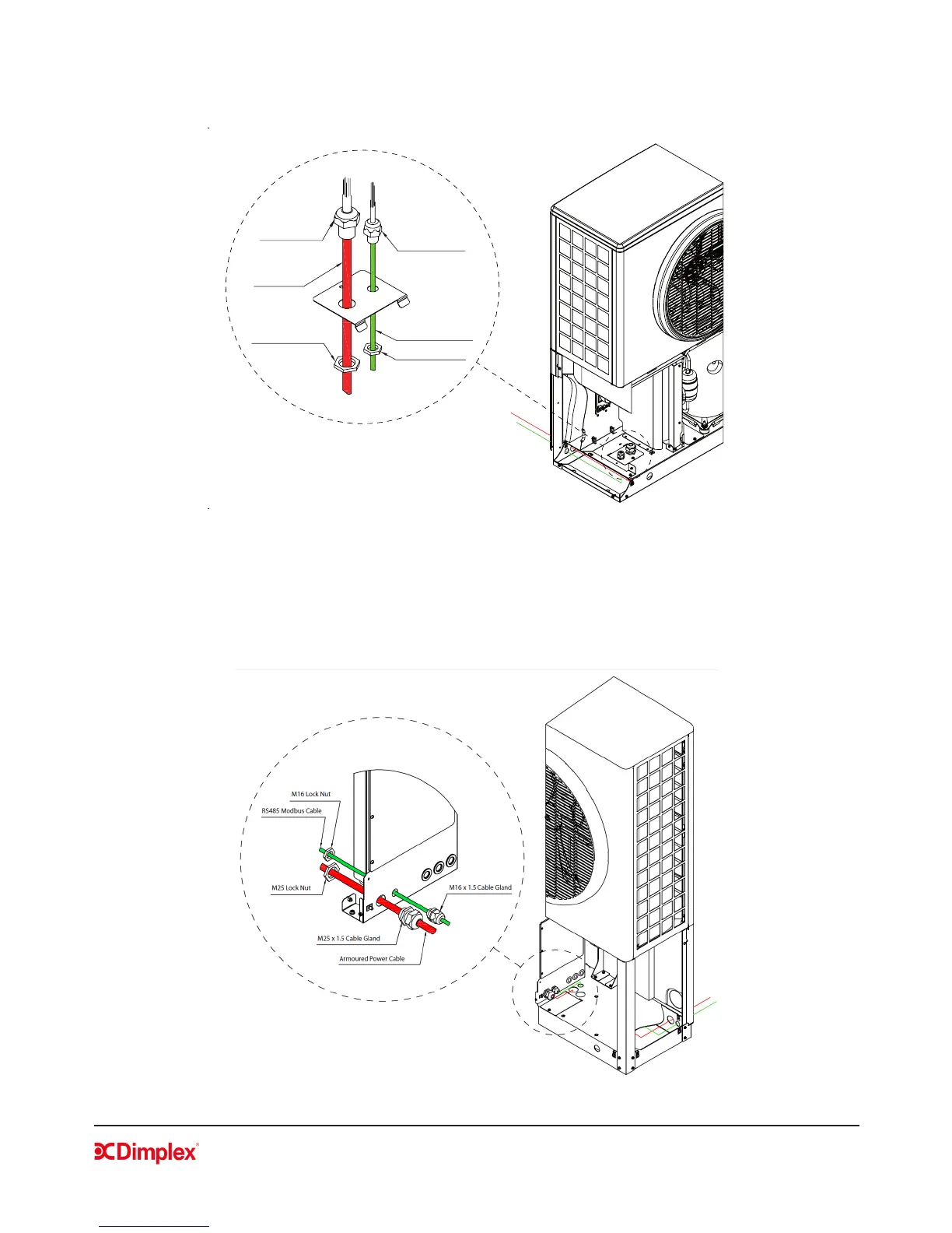
• For conguration 1, the cables are fed through the holes at the back of the heat pump and directly
inside the electrical box through the base of the heat pump (see gure 11).
Figure 11: Electrical cabling conguration 1
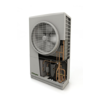
• For conguration 2, the cables are fed through the holes at the back of the heat pump, up through the
holes in the base of the heat pump and then from outside the electrical box through the cable glands
(see gure 12).
Figure 12: Electrical cabling conguration 2
M16X1.5 Cable
Gland
RS485 Modbus Cable
M16 Lock Nut
M25x1.5 Cable
Gland
Armoured Power
Cable
M25 Lock Nut