3
Manual Controls - With Remote Accessory
(Hand held or Wall Mounted)
The replace with the Remote Option has the same manual
controls with the addition of the Remote Control Receiver
(BFRC-KIT). The Remote Receiver Switch Board which will
work in conjunction with the original controls.
The remote control operation can be adjusted, depending
on the season and desired effects, by toggling the main
mode selector switch built into the replace. The position
of the switch will dictate the available functions that the
remote control will cycle through.
!
NOTE: The original controls will override all other
settings, both the Mode Selector Switch as well as the
Main On/Off Switch. (Figure 2)
A. Manual Selection Switch
Switches the operation of the replace between the
different modes of the replace:
OFF (center): Makes the unit inoperable.•
MANUAL (top): All functions of the replace are •
controlled by the On and Off buttons as described above
(Figure 2B & C).
REMOTE (bottom): All functions of the replace are •
controlled by the Remote Control.
B. Off Button
Pressing this button toggles sequentially through the three
levels of the replace. (Only when the selection switch is in
the Manual Position)
Mode Selector Set at “O”: Only Flame Effect at all 3 •
levels.
Mode Selector Set at “--”: Pressing once activates •
Level 1 - Flame effect only, two and three times
activates Level 2 - Flame effect and Purire™.
Mode Selector Set at “=”: Pressing once activates •
OPERATION
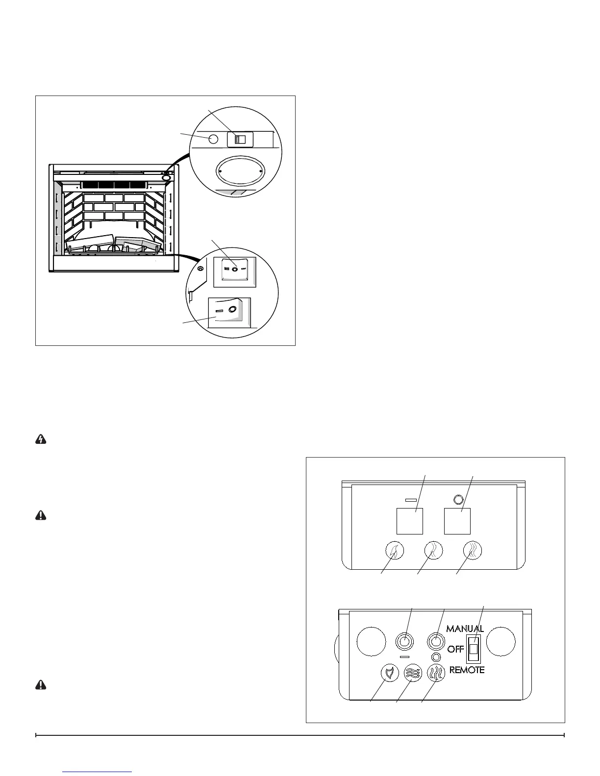
Manual Controls - Without Remote Option
The replace can be controlled by the manual switches
located on the replace (Figure 1).
Figure 1
Main Power Switch - Energizes rebox and ame.
Mode Selector Switch:
Select “o” for ame only
Select “-“ for Purire™/ame (no heat)
Select “=” for heat/Purire™/ame
Voltage Selector Switch
WARNING: Ensure that the incoming power supply
voltage matches the setting of the voltage selector
switch.
!
NOTE: The voltage selector switch is located inside
the exhaust panel on the top right hand corner (Figure
1).
CAUTION: When changing the voltage selector switch
from 240 volts to 120 volts ensure that the power supply
is turned off.
!
NOTE: Carefully insert a at head screwdriver inside
the exhaust panel to change the switch from 240 volts
(230 position) to 120 volts (115 position).
Resetting the Temperature Cutout Switch
The heater on this replace is protected with a safety device
to prevent overheating. Should the heater overheat, a red
light (Figure 1) will be activated and an automatic cut out
will turn the heater off. The heater will re-activate once the
heater has cooled. The overheat cutout will be triggered if
the lter is dirty.
CAUTION: If you need to continuously reset the heater,
disconnect power and call Dimplex customer service at
1-888-DIMPLEX (1-888-346-7539).
Over Heat Indicator
Main On/Off Switch
Mode Selector Switch
Figure 2
A
B
C
D
E F
B
C
D
E
F
Original Version
2010 Update
Voltage Selector Switch