4
www.dimplex.com
FRAMING DIMENSIONS
Rough-In Framing Dimensions Firebox Dimensions Rough-In Corner Framing
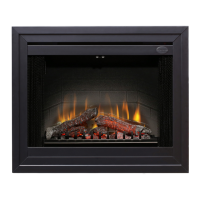
This replace is a zero clearance design. No combustibles can be placed on the top surface of the replace. Combustibles
may be installed to the edge of the unit. Four mounting anges on the sides of the unit are provided to facilitate installation.
Insulation and vapor barrier should be placed a minimum of 2” (5.1 cm) from the unit.
MOUNTING FLANGES
SECTION A: INSTALLATION INFORMATION
Figure 1
Figure 2
Model A B C D E F G H I J K L
BF45DXP
16.0”
(40.5cm)
45.5”
(115.6cm)
33.5”
(85.1cm)
30.1”
(76.5cm)
15.3”
(38.9cm)
42.0”
(106.7cm)
44.7”
(113.5cm)
22.8”
(57.9cm)
32.7”
(83.1cm)
60.0”
(152.4cm)
42.0”
(106.7cm)
42.0”
(106.7cm)
BF39STP/DXP
16.0”
(40.5cm)
39.5”
(100.3cm)
33.5”
(85.1cm)
30.1”
(76.5cm)
15.3”
(38.9cm)
36.0”
(91.4cm)
38.7”
(98.3cm)
22.8”
(57.9cm)
32.7”
(83.1cm)
54.0”
(137.2cm)
38.0”
(96.5cm)
38.0”
(96.5cm)
BF33STP/DXP
15.0”
(38.1cm)
33.5”
(85.1cm)
29.5”
(75.0cm)
25.7”
(65.3cm)
14.3”
(36.3cm)
29.6”
(75.2cm)
32.8”
(83.3cm)
18.8”
(47.8cm)
28.5”
(72.4cm)
48.0”
(121.9cm)
34.0”
(86.4cm)
34.0”
(86.4cm)
Air Intake Slots
There are two mounting anges located on each side of the replace insert.
From the inside of the unit, bend tabs outward and mount to the inside of the framing using suitable hardware.
Mounting
Flanges