7
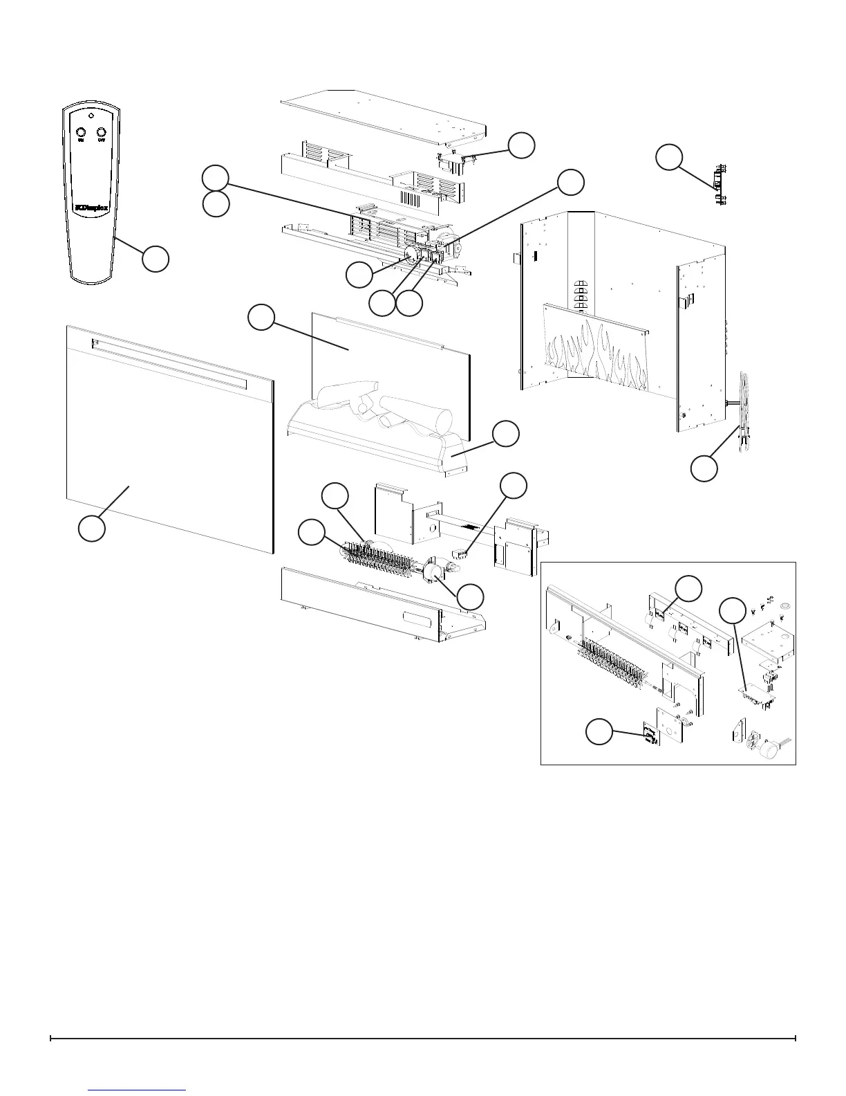
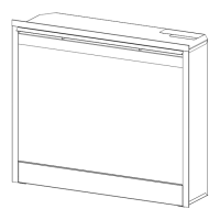
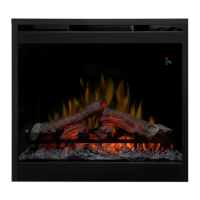
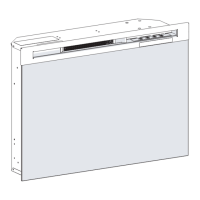
EXPLODED PARTS DIAGRAM - BF9000, 6907560100
1. Remote Control ..................3000370500RP
2. Flicker Motor ....................2000210200RP
3. Heater Assembly (with cutout) .......2200491100RP
4. Thermostat .....................2300150100RP
5. Cutout .........................2300270100RP
6. Light Assembly
Mod 0-A: 2 Socket Light Harness ....2500400500RP
Mod B: LED Light Assembly ........9600810100RP
7. Heater Switch ...................2800070700RP
8. 3-Position Switch .................2800071100RP
9. Remote Control Receiver ..........3000380200RP
10. Terminal Block ...................4000150100RP
11. Power Cord .....................4100040300RP
12. Flicker Rod .....................5901110100RP
13. Partially Reective Glass ..........5901410100RP
14. Control Knob ....................8801080100RP
15. 30” Trim Assembly with Front Glass ..6907580100RP
16. LED Logset Assembly Mod 0-A ......0440590100RP
Mod B .......0440590300RP
17. LED Driver Mod 0-A ..............3000390100RP
Mod B. . . . . . . . . . . . . 3001170100RP
18. LED Wire Harness ................2500380300RP
19. LED Log Driver Board (Mod B only) ..3001220100RP
6
16
2
3
4
5
9
10
87
13
14
12
15
11
1
17
MOD 0-A
MOD B
6
17
19