14 www.dimplex.com
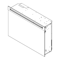
ASSEMBLY PART PICTURES
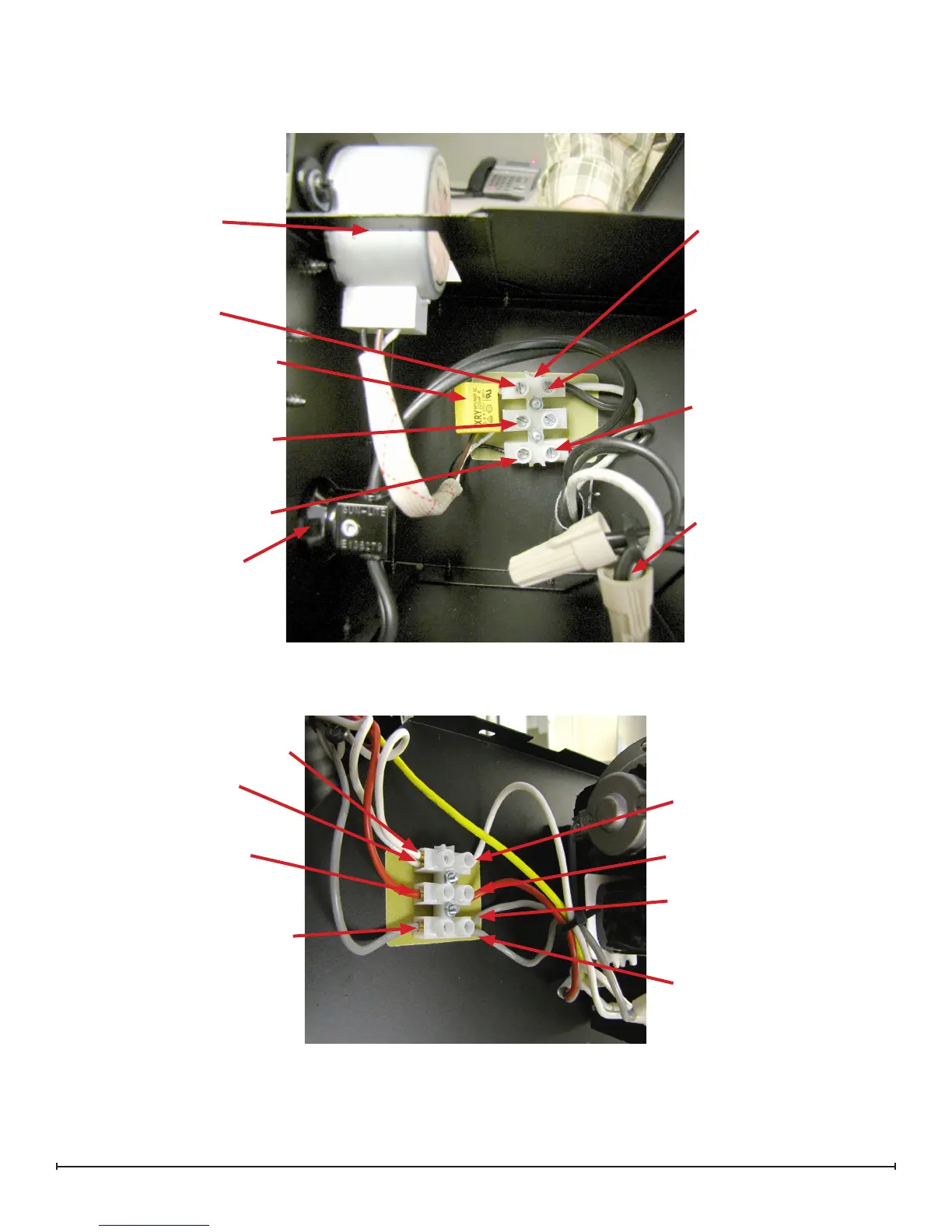
LOWER ELECTRICAL HOUSING
VIEW FROM THE BOTTOM
UPPER PANEL TERMINAL BLOCK CONNECTIONS
Flicker Motor
Capacitor - Connects to the ter-
minals with the brown and white
wires from the icker motor
Flicker Motor Connection
- Black Single
Light Socket
Lower Terminal Block
Power Cord or Hardwire
Internal Connection
Light Harness Connection
- Neutral
Light Harness Connection
- Live
Flicker Motor Connection -
White (with capacitor wire)
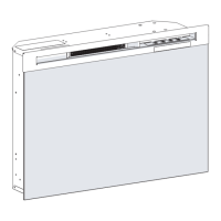
Flicker Motor Connection -
White (with capacitor wire)
White - Connects to a piggy back
connection on JP3 prong on
circuit board
Long white connects to
lower electrical housing
Red - Connects to the Inside/
middle prong on heat on/off
switch
Grey - Connects to the Thermostat
White - “Piggy-backed” to
white jumper from bottom
prong on the element
Red - From High Temperature
Cutout
Grey - From High Temperature
Cutout
Grey - To Blower motor outside
prong.