16 www.dimplex.com
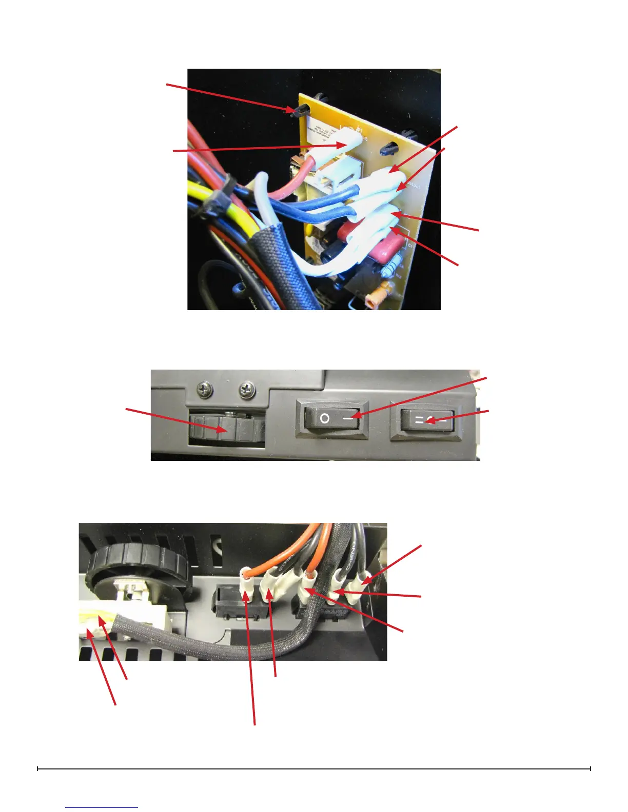
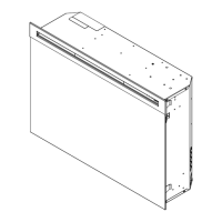
REMOTE CONTROL RECEIVER BOARD CONNECTIONS
VIEW FROM THE TOP RIGHT SIDE
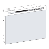
THERMOSTAT DIAL, HEATER AND 3-POSITION SWITCHES
EXTERIOR VIEW OF SWITCH PANEL
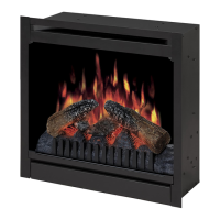
THERMOSTAT DIAL, HEATER AND 3-POSITION SWITCHES
INTERIOR VIEW – BACK SIDE OF SWITCH PANEL
Stand-Off Clips (4) - Attaching
receiver board to housing
JP1 - Connects to inside
prong of 3-Position Switch
Switch Output (Black) to outside
prong of 3-Position Switch
Switch Output (Black “Piggy
Back”) to “Piggy Back” Con-
nection on Outside Prong on
Heater On/Off Switch
JP3 (White) from upper
terminal block
JP3 (White “Piggy Back”)
from lower electrical housing
Thermostat Dial
Heater Switch
O - Off -- On
3-Position Switch
= Remote Control
O Off
-- Manual Control
Yellow from Heating
Element
Grey from Upper
Panel Terminal Block
Inside Prong (Red) connects
to Upper Terminal Block
• Outside Prong (Black) connects to
Lower Electrical Housing
• Outside Prong (Black - “Piggy Back”)
to Switch Output on Receiver Board
Outside Prong (Black) connects to
Switch Output (Black “Piggy back”)
on Receiver Board
Middle Prong (Black) connects to
Black from lower electrical housing
Inside Prong (Red) connects to JP1
on Receiver Board