EN-4 451905.66.01a · FD 0102 www.glendimpex.de
English DHW 300 - DHW 300+
2.3 Safety and control devices
The domestic hot water heat pump is equipped with the follow-
ing safety devices:
High pressure switch (HP)
The high pressure switch protects the heat pump against unac-
ceptably high operating pressure in the refrigerant circuit and
switches the heat pump off in the event of a fault. The heat
pump restarts with a time delay when the pressure in the refrig-
erant circuit has dropped again.
Safety temperature limiter for electric heater (STL)
The STL prevents impermissibly high temperatures from devel-
oping in the domestic hot water cylinder.
The electric heater switches off if the set switching value
(99 °C) is exceeded.
The electric heater cannot be switched on again until the do-
mestic hot water temperature has decreased to ≤ 90 °C and the
reset button (see illustration) on the STL (under flange cover) is
pressed (this must only be done by qualified personnel).
The domestic hot water heat pump is also equipped with the
following regulation and control devices:
Heat pump temperature controller
Temperature control in the domestic hot water cylinder and the
regulation for compressor operation is carried out by the con-
trol electronics. Electronic sensors measure the water tempera-
ture, which is regulated based on the setpoint. The desired tem-
perature level (setpoint) is set via the keypad on the control
panel.
Air intake temperature
The sensor connected to the controller measures the tempera-
ture in the domestic hot water heat pump directly in front of the
evaporator (air intake temperature). If the set switching value is
not reached (7 ±1 °C, reset value 2 K,
delay 30 min), the domestic hot water preparation is switched
automatically from heat pump operation to heating element
operation.
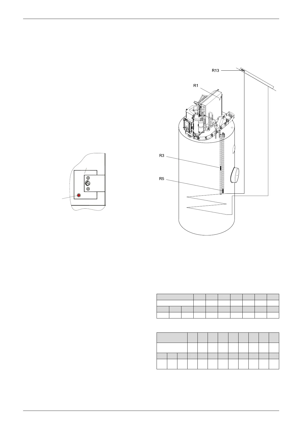
2.4 Temperature sensor
2.4.1 Temperature sensor installation
position
R1 Air inlet sensor
R3 Domestic hot water sensor
R5 Domestic hot water renewable sensor (optional)
R13 Renewable sensor (optional)
2.4.2 Measured values temperature sensor
Measured values NTC 10 sensor (R1, R3, R5)
Measured values PT 1000 sensor (R13)
85°
30°
F17
STB
Rückstellknopf
Temperature in °C -20 -15 -10 -5 0 5 10
NTC-10 in kΩ 67.7 53.4 42.3 33.9 27.3 22.1 18.0
15 20 25 30 35 40 45 50 55 60
14.9 12.1 10.0 8.4 7.0 5.9 5.0 4.2 3.6 3.1
Temperature
in °C
-30 -20 -10 0 10 20 30 40 50
PT 1000 in kΩ
0.88
2
0.02
2
0.96
1
1.00
1.03
9
1.07
8
1.11
7
1.15
5
1.19
4
60 70 80 90 100 110 120 130 140 150 160
1.23
2
1.27
1
1.30
9
1.34
7
1.38
5
1.42
3
1.46
1
1.49
8
1.53
6
1.57
3
1.61
1