17
11.2
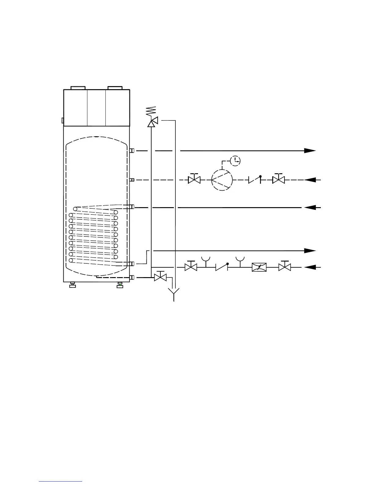
Hydraulic Plumbing Diagram
1 Shut-off valve 6 Drain valve
2 Pressure-reducing valve 7 Diaphragm safety valve
3 Test valve
(to be mounted above tank edge)
4 Non-return valve 8 Circulating pump
5 Manometer connection 9 Drain
*
on HPWH without internal heat exchanger, the connections for the suppl. heat source are dispensed
with, i.e. no heating water flow and return lines)
1
1
8
4
1
7
Warmwasser
Heizwasservorlauf
Zirkulation
(wenn erforderlich)
Heizwasserrücklauf
Kaltwasseranschluß nach DIN 1988
9
6
1
5
4
3
2
*
*
Hot water
Hot water flow
Circulation
(if required)
Hot water return
Cold water connection acc. to DIN 1988