Fitting Product - see Fig. 3 - 10
There are three possible mounting methods
1. Surface Mounting
2. Partial Recessed (Not on 74" Models)
3. Flush Mount
Surface Mounting (34" & 74" Models)- see
Fig. 3 & 4
CAUTION: Two people will be required for various steps
of this procedure.
1. Determine the mounting location of the unit so that
the wall-mounting bracket can be installed into a
minimum of 2 wall studs for the 34" Models and 4 wall
studs for the 74" Models
!
NOTE: It is recommended that the mounting bracket be
installed 56 in. (142 cm) off of the ground to maintain an
optimized viewing angle of the ame.
2. Hold the wall mounting bracket, with the spirit level on
the top, on the wall so that the bubble on the level is
centered between the two black lines.
3. Mark the 4 mounting screw locations, on the wall,
ensuring that the wall bracket stays level (Fig. 3)
marked (A).
4. In locations where the screws are being installed only
into drywall, install the supplied wall anchors before
installing the screw (predrill if required).
5. Secure the wall bracket to the wall using the supplied
1 ½ in. (3.8 cm) mounting screws and washers into the
wall and/or wall anchors.
6. Install the bottom support bracket to the wall centered
with the wall mounting bracket, using the appropriate
mounting hardware, 13 ¾" (350 mm) below the wall
mounting bracket (Fig. 3) marked (B).
7. Remove the center screw from the bottom of the
replace. (Fig. 4)
8. Hang the replace from the bracket.
9. Install the previously removed screw through the
bottom support bracket into the replace.
10. Refer to Front Glass Installation section for nal
installation procedures.
Surface Mounting (50" Models) - see Fig. 5 & 6
CAUTION: Two people may be required for various
steps of this procedure.
1. Choose a location which has a minimum of two wall
studs available for mounting.
2. Remove the partially reective glass from the replace:
• Lay replace on its back.
• Remove two Phillips screws from each of the two glass
brackets (Fig. 5) marked (A).
• Remove glass brackets (Fig. 5) marked (B).
• With one hand keeping pressure on the partially
reective glass, tilt the replace upright and slightly
forward to allow the partially reective glass to fall out
of the inside framing.
CAUTION: Partially reective glass is not tempered. Do
not bump or drop the partially reective glass to avoid
breakage and personal injury.
• Remove partially reective glass from replace.
3. Position the replace on a wall in the position where
it will be mounted (Fig. 6). Use a spirit level (one is
supplied) to ensure that replace is level on the wall.
4. Ensuring that at least two key-holes line up with a wall
stud (key-holes are spaced at 4 in. (10.2 cm) centers)
(Fig. 6) marked (A), mark the location of four screw
locations on the wall (through key-holes).
5. Remove fireplace from wall and store in a safe place
away from traffic.
6. Where marked screw locations do not line up with a
wall stud, insert (screw in) one of the two supplied wall
anchors (predrill if required). Repeat if only two screws
line up with a wall stud.
7. Screw all four supplied #8, 1 ½ in. (3.8 cm) square head
mounting screws and washers into the wall and/or wall
anchors leaving ¼ in. (6.5 mm) of thread.
8. Align chosen key-holes with screws and hang replace
on the wall. Screw heads and washers will t through key-
holes and replace will slide down into place (screws will
slide into narrow part of key-holes).
9. Tighten all four mounting screws down on replace
chassis.
10. Screw the two supplied #8 square head screws through
two of the permanent mounting holes (Fig. 6) marked
(C) which align with a wall stud.
11. Carefully replace and install partially reflective glass and
glass brackets using screws from step 1.
12. Refer to Front Glass Installation section for nal installation
procedures.
Partial Recessed (Not possible on 74" Models)- see
Fig. 7 & 8
CAUTION: Two people may be required for various steps
of this procedure.
1. Prepare a wall with a framed opening for the correct
model (Fig. 7)
• 34" Models: 30 ½ in. (77.5 cm) wide x 16 ½ in. (42 cm)
high
• 50" Models: 46 ½ in. (118.1 cm) wide x 16 ½ in. (42 cm)
high
!
NOTE: The sizing has allowed for ¼ in. (6.4 mm) around
the replace insert for ease of installation. This replace does
not require any additional venting.
2. Choose your method of supplying power to the unit:
• Plug in (you may run the power cord out of the framed
wall opening to an existing outlet or install an outlet on a
nearby wall stud within the wall).
• Hard wire the replace.
WARNING: Do not attempt to wire your own new outlets
or circuits. To reduce the risk of re, electric shock or injury to
persons, always use a licensed electrician.
WARNING: Ensure that the circuit on which the replace
is to be installed has the power cut off at the service panel
until installation is complete.
3. Lift replace and insert into opening (Fig. 8).
4. Use spirit level (supplied) to level the replace within the
framing. Adjust as required.
5. Drive four supplied mounting screws through the four
mounting holes located in each corner of the replace
chassis, into wall studs (Fig. 8).
6. Refer to Front Glass Installation section for nal installation
procedures.
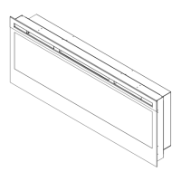
Flush Mount- see Fig. 9 & 10
CAUTION: Two people will be required for various steps
of this procedure.
1. Prepare a wall with a framed opening for the correct
model (Fig. 9)
• 34" Model: 33 in. (83.8 cm) wide x 18 ½ in. (47 cm)
high
 Loading...