Thermal Safety Cut-out
The built-in overheat cut-out, switches off the appliance
automatically in the event of a fault! Should this occur
switch off the appliance or disconnect the mains plug
from the socket.
Remove any obstructions which may have caused the
overheating. After a short cooling down phase, the
appliance is ready for use again! If the fault should occur
again, contact your local dealer!
WARNING: In order to avoid a hazard due to inadvertent
resetting of the thermal cut-out, this appliance must not be
supplied through an external switching device, such as a
timer, or connected to a circuit that is regularly switched
on and off by the utility.
Maintenance
WARNING: ALWAYS DISCONNECT FROM THE POWER
SUPPLY BEFORE ATTEMPTING ANY MAINTENANCE.
Light Emitting Diode
This re is tted with LED (Light Emitting Diode) lamps. These
LED lamps are maintenance-free and should not require
replacing during the life of the product.
Cleaning
WARNING: ALWAYS DISCONNECT FROM THE POWER
SUPPLY BEFORE CLEANING THE HEATER.
For general cleaning use a soft clean duster – never use
abrasive cleaners. The glass viewing screen should be
cleaned carefully with a soft cloth.
DO NOT use proprietary glass cleaners.
To remove any accumulation of dust or uff, the soft brush
attachment of a vacuum cleaner should occasionally be
used to clean the outlet grille of the fan heater.
WARNING: do not operate the product without the grille
and outer glass in position as this may effect the operation
of the heater.
Recycling
At the end of the electrical products useful life, it
should not be disposed of with household waste.
Please recycle where facilities exist. Check with
your Local Authority or retailer for recycling advice
in your country.
After Sales Service
Should you require after sales service or should you need
to purchase any spares, please contact the retailer from
whom the appliance was purchased or contact the
service number relevant to your country on the warranty
card.
Please do not return a faulty product to us in the rst
instance as this may result in loss or damage and delay
in providing you with a satisfactory service. Please retain
your receipt as proof of purchase.
• 50" Model : 49 in. (124.5 cm) wide x 18 ½ in. (47 cm)
high
• 74" Model: 73 in. (185.4 cm) wide x 18 ½ in. (47 cm)
high
!
NOTE: It is recommended that the bottom
of the unit not be mounted higher than 40 in.
(102 cm) from the ground to maintain an optimized viewing
angle of the ame.
WARNING: Do not attempt to wire your own new outlets
or circuits. To reduce the risk of re, electric shock or injury to
persons, always use a licensed electrician.
WARNING: Ensure that the circuit on which the replace
is to be installed has the power cut off at the service panel
until installation is complete.
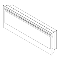
2. Lift replace and insert into opening. The replace’s
mounting trim should be ush against the wall (Fig. 10).
3. Use the supplied spirit level to level the replace within
the framing, adjust as required.
4. Drive four supplied mounting screws through the four
mounting holes located on the inside surface of the
replace chassis, into wall studs (Fig. 10).
5. Refer to Front Glass Installation section for nal installation
procedures.
Front Glass Installation- see Fig. 11 & 12
1. Pour and evenly distribute the supplied media in the
media tray of the firebox (Figure 11).
2. Carefully mount front glass assembly so that the front
glass hooks hang on the front glass mounts on the
fireplace (Figure 11).
3. Use the supplied four Phillips sheet metal screws to fasten
the glass assembly tabs to the fireplace (Figure 12).
Remote Control - See Fig. 2
The maximum range of use is ~ 5metres.
NOTE: It takes time for the receiver to respond to the
transmitter.
NOTE: The reciever for the remote control is located in
the display, aim the remote control in this direction when
inputting commands.
Do not press the buttons more than once within two seconds
for correct operation.
Battery Information - See Fig. 2
1. To activate the remote control remove the clear battery
isolation strip at the base of the remote control, which is used
to ensure your remote control reaches you fully charged.
2. To replace the remote control battery, turn over the
remote control and follow the diagram embossed on the
remote control
3. Only use CR2025 or CR2032 size of batteries.
Dimplex Millbrook House,
Grange Drive, Hedge End,
Southampton, SO30 2DF
© Glen Dimplex Heating and Ventilation.
All rights reserved. Material contained in this publication may not be reproduced in whole or in part, without prior permission
in writing of Glen Dimplex Heating and Ventilation.
Tel: 0344 879 3588
Republic of Ireland Tel: 01 8428 222
www.dimplex.co.uk
 Loading...