DN3PD1
Function description
10 18-09-27 / 33pd02-V0743
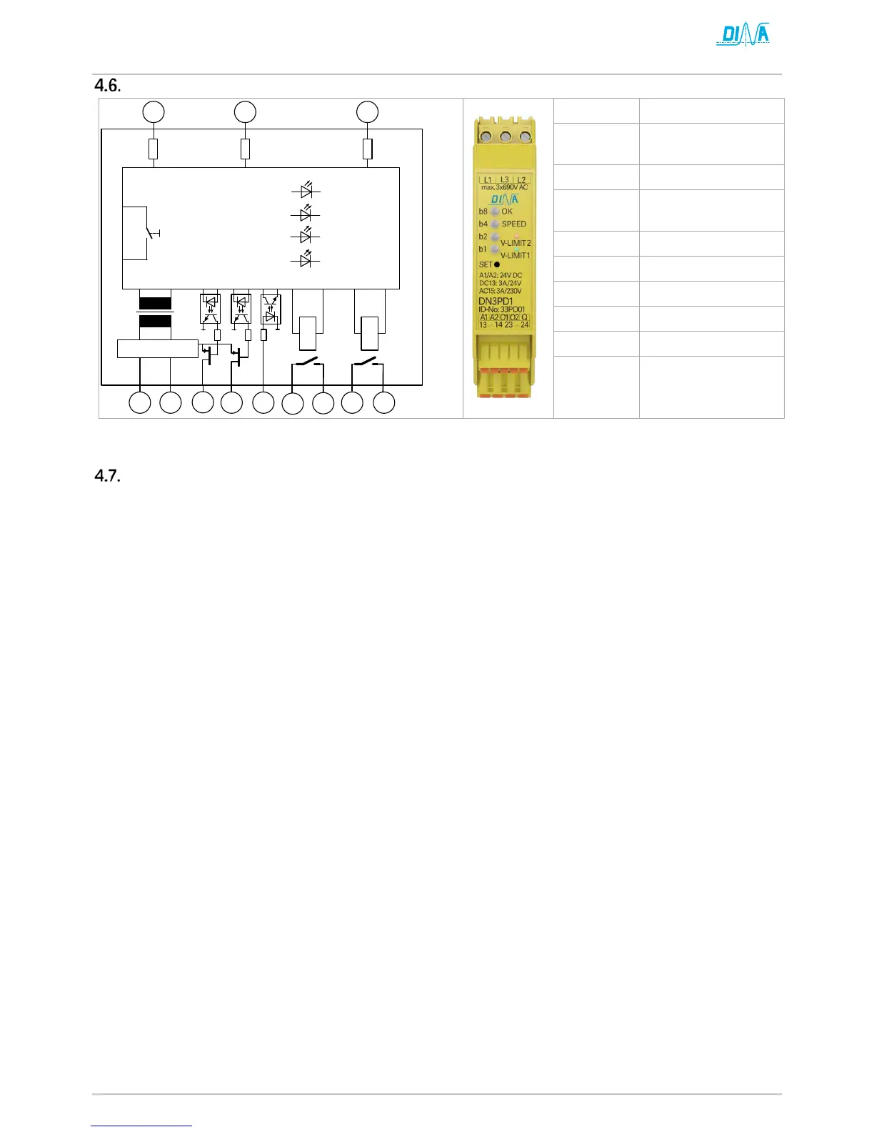
Schematic, operating element and display
A2 0V
Q Acknowledgment in-
put
O1, O2 Diagnostics outputs
13-14/23-24 Enabling contacts
SET Configuration button
b1, b2, b4, b8 parameter 1-15
OK Ready for operation
SPEED Speed Status
Terminal description
A1/ A2 Power supply 24V DC
L1, L2, L3 Measuring inputs are to be connected directly to the motor, without switching contacts between.
Q Acknowledgment input can be parameterized, manually or automatically
13/14, 23/24 Enabling contacts (2 NO-contacts). These switch off immediately if the parameterized speeds are
undershot or exceeded or internal or external errors.
13/14, 23/24 are to be used in such a way that the intended safety function, e.g. emergency stop is
executed.
O1, O2 Digital positive switching semiconductor outputs for the transmission of switching states to a
higher-level control for diagnostic tasks.