EasyManua.ls Logo

DINA DN3PD1 - 8 Diagnostics; 8.1 Error Report

DINA DN3PD1
20 pages
Print Icon
To Next Page IconTo Next Page
To Previous Page IconTo Previous Page
Loading...
DN3PD1
Diagnostics
16 18-09-27 / 33pd02-V0743
8 Diagnostics
The 2-color LEDs (b1, b2, b4, b8) indicate operational readiness, switching status, internal and external errors.
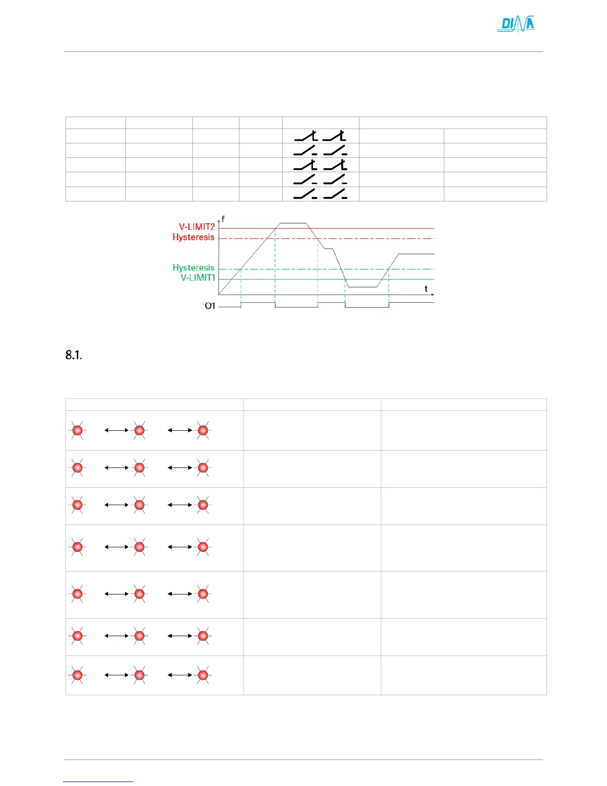
The semiconductor output O1 is switched on when the frequency is within the parameterized range. See Fig. 8-1
The semiconductor output O2 indicates the operational readiness. This switches off in case of an error.
LED OK
LED SPEED
O1
O2
13/14, 23/24
Status
green
green
24V
24V
acknowledged
in range
green
off
0V
24V
not acknowledged
out of range
green
flashing green
0V
24V
acknowledged
out of range
green
off
24V
24V
not acknowledged
in range
flashing red
off
0V
0V
error
see error report
Fig. 8-1
Error report
The red flashing LED OK signals an error condition.
The flashing variations for different causes of faults are shown below.
flashing variation
possible cause
remedy
1s
1x
1x
1s
1x
incorrect power supply
UB < 20V or > 32V
UB=20.5V-26,5V DC
1s
2x
… 2x
1s
… 2
x
(V-LIMIT 2) < (V-LIMIT 1)
(V-LIMIT 2 10%) > (V-LIMIT 1)!
1s
… 3x
… 3x
1s
… 3x
incorrect acknowledge signal
Q < 200ms or > 10s
Q ≥200ms, <10s
1s
… 4x
… 4x
1s
… 4x
open-circuit on L1, L2, L3
check on
short circuit
cross-connection
wire break
1s
… 5x
… 5x
1s
… 5x
single-channel measuring
check on
short circuit
cross-connection
wire break
1s
… 6x
… 6x
1s
… 6x
relay error
check on external error
switch off, switch on
exchange
1s
… ≥7x
… ≥7x
1s
… ≥7x
internal error
switch off, switch on
exchange

Other manuals for DINA DN3PD1