EasyManua.ls Logo

Dinstar DAG1000-4S - User Manual

Dinstar DAG1000-4S
2 pages
Print Icon
To Next Page IconTo Next Page
Loading...
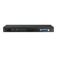
Note: DAG1000-4S has no network speed indicator.
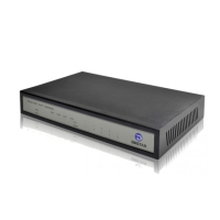
DAG1000-4S
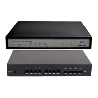
Connection Diagram for DAG1000-4S
Network Connection
Network Connection
Network Cable Network Cable
Network Cable
Network Cable
ADSL
ADSL
Power Adapter
Power Adapter
Telephone Line (RJ11)
Telephone
Power Connection
Power Connection
Telephone Connection
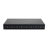
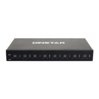
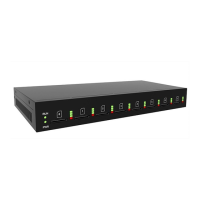
Connection Diagram for DAG1000-8S
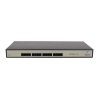
DAG1000-8S
Power Indicator
Power Indicator
Running Indicator
Running Indicator
Network Link Indicator
Network Speed Indicator
Network Link Indicator
Power Jack
Power Jack
FXS Port
FXS Port
Reset Button
Reset
Button
LAN Port
LAN Port
WAN Port
WAN Port
Telephone In-use
Indicator
Telephone In-use
Indicator
Indicator
PWR
RUN
FXS
WAN/ LA N
Definition
Power Indicator
Running Indicator
Telephone In-use
Indicator
Network Link
Indicator
Network Speed
Indicator
Status
On
On
On
Off
Off
Off
Off
Off
Slow
Flashing
Fast
Flashing
Green
Flashing
Description
The gateway is powered on
The gateway is powered off
or there is no power supply
The gateway is running properly
If there is a SIP account registered
successfully, the indicator is fast flashing
The gateway is running improperly
FXS port is currently occupied by a call
FXS port is idle or faulty
The gateway is properly connected to
network
The gateway is not connected to network or
network connection is improper way
Work at 100Mbps
Work at 10Mbps
Indicators and Ports
3
Installation Instructions
5
Installation Attentions
4
Description of Indicators
2
Number of Ports
1
DAG1000-4S
DAG1000-8S
Thanks for Choosing Dinstars VoIP Gateway!
Please read this guide carefully before installing the gateway. If you need any technical
support, please contact us.
Tel: +86 755 61919966
Email: support@dinstar.com
Website: www.dinstar.com
Quick Installation Guide
Telephone Line (RJ11)
Telephone
Gateway
Port Type
DAG1000-4S
DAG1000-8S
1
1
WAN
1
3
LAN
4
8
FXS
Anti-jamming: to reduce the interference with telephone calls, it’s highly
recommended that telephone lines connected to the gateway should be placed
away from power cables.
Power supply: the power adapter of the gateway accepts DC input voltage of 12V.
Please ensure safe and stable power supply.
Network bandwidth: please ensure there is enough network bandwidth so as to
guarantee stabilized running of the gateway.
Temperature and humidity: to avoid any accident that might cause malfunction , it’s
advised to install the gateway in an equipment room where temperature and
humidity are appropriate.
Ventilation: to avoid overheating, please do not pile up the gateway with other
devices and make sure the gateway has good ventilation around.
Mechanical load: please make sure the gateway is placed steadily to avoid damage.
It’s highly advised to horizontally place the gateway on a flat surface or a cabinet.
Power Indicator
Running Indicator
PC
LAN
PC
LAN
AUX2
AUX2
Question and Answer IconNeed help?

Do you have a question about the Dinstar DAG1000-4S and is the answer not in the manual?

Overview

This document describes the Dinstar VoIP Gateway, available in DAG1000-4S and DAG1000-8S models, designed for IP communication solutions.

Function Description

The Dinstar VoIP Gateway facilitates voice over IP (VoIP) communication, connecting traditional telephone lines to an IP network. It allows for the registration of SIP accounts and provides FXS ports for connecting analog telephones. The gateway supports various network configurations and offers features for monitoring its operational status and network connectivity.

Important Technical Specifications

Models:

  • DAG1000-4S: Features 1 WAN port, 1 LAN port, and 4 FXS ports.
  • DAG1000-8S: Features 1 WAN port, 3 LAN ports, and 8 FXS ports.

Power Supply: The gateway accepts a DC input voltage of 12V. Users must ensure a safe and stable power supply.

Indicators: The device includes several LED indicators to display its status:

  • PWR (Power Indicator):
    • On: Gateway is powered on.
    • Off: Gateway is powered off or no power supply.
  • RUN (Running Indicator):
    • Slow Flashing: Gateway is running properly.
    • Fast Flashing: A SIP account is successfully registered.
    • Off: Gateway is running improperly.
  • FXS (Telephone In-use Indicator):
    • On: FXS port is currently occupied by a call.
    • Off: FXS port is idle or faulty.
  • WAN/LAN (Network Link Indicator):
    • Green Flashing: Gateway is properly connected to the network.
    • Off: Gateway is not connected to the network or the connection is improper.
  • WAN/LAN (Network Speed Indicator - DAG1000-8S only):
    • On: Works at 100Mbps.
    • Off: Works at 10Mbps.
    • Note: DAG1000-4S does not have a network speed indicator.

Default IP Address: The default IP address for the gateway is 192.168.11.1. The default username and password for the web management system are "admin".

Usage Features

Installation:

  • Anti-jamming: To minimize interference with telephone calls, it is recommended to keep telephone lines away from power cables.
  • Network Bandwidth: Ensure sufficient network bandwidth for stable gateway operation.
  • Environment: Install the gateway in an equipment room with appropriate temperature and humidity to prevent malfunctions.
  • Ventilation: Avoid stacking the gateway with other devices and ensure good ventilation to prevent overheating.
  • Mechanical Load: Place the gateway steadily on a flat surface or in a cabinet to prevent damage.

Configuration:

  • PC IP Address Modification: Before logging into the Web Management System, the PC's IP address must be modified to be in the same network segment as the gateway (e.g., 192.168.11.XXX). This involves accessing network properties, selecting "Internet Protocol Version 4 (TCP/IPv4)", and manually entering an IP address, subnet mask (255.255.255.0), and default gateway (192.168.11.1).
  • Web Management System Access: Open a web browser and enter the gateway's default IP address (192.168.11.1). Log in using the default username and password "admin".
  • Gateway IP Address Modification: Within the Web Management System, navigate to 'Network → Local Network' to change the gateway's IP address and DNS server settings.
  • SIP Server Configuration: In the Web Management System, go to 'SIP Server' to enter the SIP server address for registration. Then, under 'Port', add SIP accounts by inputting the SIP User ID, authentication ID, and password assigned by the SIP server.
  • Saving Changes: After making configurations, click 'Save' and restart the gateway for the new settings to take effect.

Basic Operations (via telephone keypad):

  • Query LAN IP Address: Dial *158#.
  • Query WAN IP Address: Dial *159#.
  • Query FXS Port Telephone Number: Dial *114#.
  • Restore Default IP Address, Username, and Password: Dial 165000000#.
  • Restart Gateway: Dial *111#.

Maintenance Features

Restore Factory Default Settings: There are two methods to restore the gateway to factory defaults:

  1. Via Telephone Keypad:
    • Dial 166000000#.
  2. Via RST Button and Web Management System:
    • Press the RST button on the device for 7 seconds.
    • Log in to the gateway's Web Management System.
    • Navigate to 'Tools → Factory Reset'.
    • Click 'Apply' and restart the gateway.

Troubleshooting:

  • If the gateway is running improperly, the RUN indicator will be off.
  • If the network connection is improper, the WAN/LAN Network Link indicator will be off.

For detailed configuration and parameter explanations, users should refer to the user manual or contact Dinstar's technical support.

Dinstar DAG1000-4S Specifications

General IconGeneral
BrandDinstar
ModelDAG1000-4S
CategoryGateway
LanguageEnglish

Related product manuals