7
403.FORD6 3.24 2013 Ford Taurus (40-Bit)
©2022 VOXX•DEI LLC. All rights reserved.
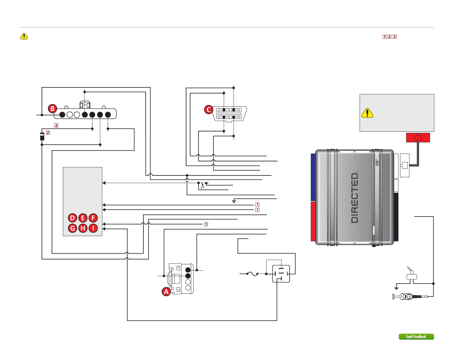
Refer to "Pre-installation and application warnings" for important information, such as the description of each special note referenced in the diagram ( ).
(+) Ignition Output: Yellow: 8
(+) Keysense: Pin 5
(+) Ignition:
Pin 1
(+) 12V Input: Brown: 7
HS CAN Low: Orange/Brown: 6
Data RX: Orange/Black: 11
(-) Parking Lights Output: Blue/Red: 12
Data TX: Yellow/Black: 10
(-) Lock Output: Green/Black: 2
(-) Unlock Output: Red/Black: 4
(+) Accessory/Keysense Output: Gray/Black: 7
(+) Starter Output: Gray: 6
(-) Trunk Hatch Release/Power Liftgate Output: Violet/Brown: 9
HS CAN High: Orange/Green: 5
MS CAN Low: Tan: 4
MS CAN High: Tan/Black: 3
(+) 12V: Pin 4
(+) Accessory: Pin 6
(+) Starter: Pin 7
P.A.T.S.
(at ignition switch)
1
2
3
4
TX: Pin 3
RX: Pin 4
Wiring diagram
1 2 3 4 5 6 7
Ignition Switch
(black connector)
16
8
9
1
HS CAN Low:
Pin 14
HS CAN High:
Pin 6
MS CAN Low:
Pin 11
MS CAN High:
Pin 3
OBDII Diagnostic
(connector side view)
Refer to
“Vehicle
connections”
section for the
connector, pin and
wire color of your
vehicle.
1A Diode
6: White/Black:
(-) Hood
Remote Start Safety
Override Switch
Hood Pin
You can connect to either a
XL202 RFTD OR a SmartStart
module.
Refer to the SmartStart/XL202
Installation Notes for more
information.
Driver’s Door Trigger
RAP Off Interrupt (vehicle side): Orange/Red: 10
RAP Off Interrupt (connector side): Yellow/Red: 11
Cut
(+) 12V Input: Red: 13
(-) Ground: Black: 14
30
86 85
87
87a
Fuse 15A
(+) 12V
Note: The hood pin is
only required on vehicles
that are not equipped
with a factory hood pin.