EasyManuals Logo

Directed Electronics Ready Remote User Manual

Directed Electronics Ready Remote
70 pages
To Next Page IconTo Next Page
To Previous Page IconTo Previous Page
Page #42 background imageLoading...
Page #42 background image
38
© 2006 Directed Electronics
power wire, or the (+) terminal of the battery.
3. Operate the door lock switch/key cylinder in both directions to
determine the resistor values. If the multimeter displays zero resis-
tance in one direction, no resistor is needed for that direction.
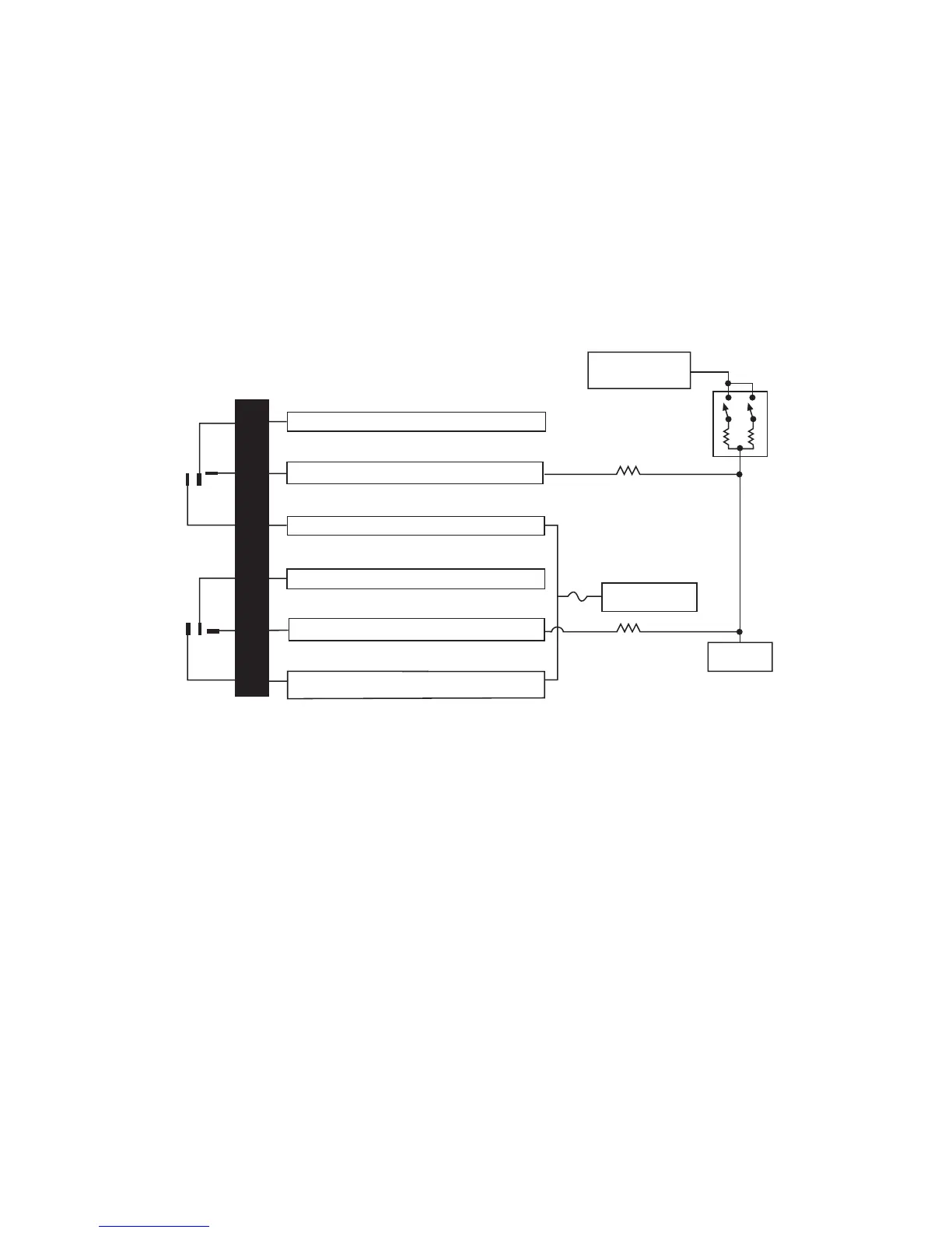
4. Once the resistor value(s) is determined, refer to the wiring dia-
gram for proper wiring.
type H: negative (-) multiplex
The system is most commonly found in Ford, Mazda, Chrysler
and GM vehicles. The door lock switch or door key cylinder
may contain either one or two resistors.
SSIINNGGLLEE--RREESSIISSTTOORR TTYYPPEE::
If one resistor is used in the door lock
switch/key cylinder, the wire will pulse ground in one direction and
resistance to ground when operated in the opposite direction.
H2/2
H2/3
H2/4
H2/5
H2/6
H2/7
LOCK
RELAY
UNLOCK
RELAY
#87
#87A
#30
#87
#87A
#30
BCM
GREEN/BLACK LOCK #30 COMMON (OUTPUT)
WHITE/BLACK NOT USED
VIOLET/BLACK LOCK #87A NORMALLY OPEN (INPUT)
BROWN/BLACK NOT USED
BLUE/BLACK UNLOCK #30 COMMON (OUTPUT)
VIOLET UNLOCK #87 NORMALLY OPEN (INPUT)
VIOLET & VIOLET/BLACK ARE COMMON AT FUSE HOLDER
15A
VEHICLE FUSED
+12 VOLT CONSTANT
LOCK RESISTOR
(IF REQUIRED)
UNLOCK RESISTOR
(IF REQUIRED)
DOOR LOCK SWITCH/
KEY CYLINDER
UNLOCK
(+)12V
CONSTANT FUSED
LOCK

Questions and Answers:

Question and Answer IconNeed help?

Do you have a question about the Directed Electronics Ready Remote and is the answer not in the manual?

Directed Electronics Ready Remote Specifications

General IconGeneral
BrandDirected Electronics
ModelReady Remote
CategoryRemote Starter
LanguageEnglish

Related product manuals