5
© 2012 Directed. All rights reserved.
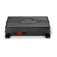
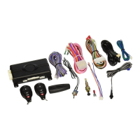
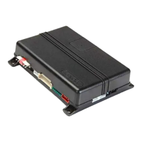
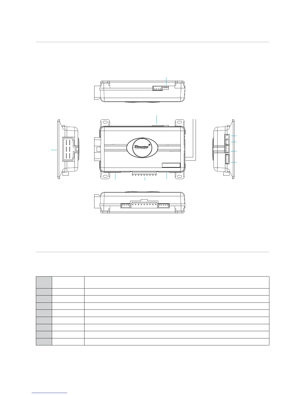
Wiring diagram
Control Button
(Valet Switch)
Door Lock/unlock
Harness
Side View
Antenna
Antenna
LED (Programming
indicator)
Parking light jumpers
Primary Harness Remote Start Harness
Heavy
Gauge
Relay
Side View
Satellite Harness
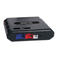
Red 4-pin port, Bitwriter/ ESP2 or D2D
4x03
Wiring connections
Main Harness (H1), 9-pin connector
H1/1
LIGHT GREEN
BLACK
(-) 200mA FACTORY ALARM DISARM
H1/2
GREEN/WHITE (-) 200mA FACTORY ALARM REARM
H1/3
YELLOW (+) IGNITION OUT (TO ALARM)
H1/4
WHITE/BLUE (-) ACTIVATION INPUT
H1/5
ORANGE (-) 500mA GROUND WHEN LOCKED/ANTI-GRIND OUTPUT
H1/6
BROWN (-) 200mA HORN OUTPUT
H1/7
RED/WHITE (-) 200mA TRUNK RELEASE OUTPUT*
H1/8
BLACK GROUND
H1/9
WHITE (+/-) LIGHT FLASH OUTPUT
* Not available on 1-button remote