Do you have a question about the Directed 5906 and is the answer not in the manual?
Details the connections for the main 6-pin harness, including power, ground, and outputs.
Details the connections for the 24-pin auxiliary/shutdown/trigger harness.
Details the connections for the 10-pin heavy gauge remote start harness.
Details the connections for the 3-pin door lock harness.
Details the connections for the 4-pin D2D harness.
Details the connections for the 3-pin Bitwriter/SmartStart harness.
Provides detailed descriptions of each wire in the main 6-pin harness.
Details connections for parking light isolation and output wires.
Describes the orange wire's function as a ground output when the system is armed.
Details descriptions for wires in the 24-pin auxiliary harness.
Details descriptions for wires in the 10-pin heavy gauge remote start harness.
Details descriptions for wires in the 3-pin door lock harness.
Details programmable features for system arming, panic mode, and confirmation chirps.
Details programmable convenience features like one-time bypass, nuisance prevention, and auxiliary outputs.
Details programmable remote start features like transmission mode, engine checking, and cranking time.
Adjusts starter output time in Tachometer mode to overcome engine start variations.
Locks or unlocks user access to feature menus and manual programming.
Sets engine runtime duration for normal remote start operations.
Adjusts starter output time in Virtual Tach mode for engine start variations.
Instructions for pairing the HD remote control via the settings menu.
Instructions for pairing the LCD remote control using its buttons and the Control Center.
Instructions for pairing LED 2-way or 1-way remote controls with the system.
Diagnosing MTS mode failures related to tachometer, E-brake, and door inputs.
| Type | Remote Starter |
|---|---|
| Range | Up to 1 mile |
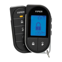
| Number of Buttons on Remote | 5 |
| Number of Remotes Included | 2 |
| Security System | Yes |
| SmartStart Compatible | Yes |
| Display Type | LCD |
| Remote Start | Yes |
| Alarm | Yes |
| Features | Keyless Entry, Trunk Release |
| Compatibility | Most vehicles |
| Remote Start Confirmation | Yes |
| Alarm Features | Starter Kill |
| Battery Life | Up to 2 years |