5
© 2016 Directed. All rights reserved.
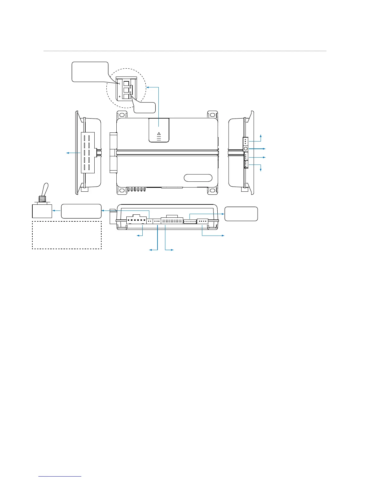
Wiring Diagram
1
10 9 8 7 6
12345
1
1 8
51
1 3
10
12
18
10
9
1
1 12
D2D Port
(for external Directed
interface module)
ON
IMPORTANT!
Remote Start Shutoff
switch must be plugged in
and in the ON position
Sensor Port 1:
Doubleguard Shock Sensor
Sensor Port 2
Thermistor/Temp Sensor
Bitwriter/Directed
SmartStart Port
Door Lock
3-pin Harness
Remote Start
8-pin Harness
Main 6-pin
Harness
(+) or (-) LIGHT
FLASH POLARITY
(10A (MAXIMUM)
FUSE JUMPER)
AUX/Shutdown
24-pin Harness
Remote Start
Shutoff Switch
RF/Control
Center Port
10A FUSE
MINI ATM
Note: Fuse is under the plastic cover and needs to
be installed for the appropriate light flash polarity.
Note: Sensor ports 1 and 2 cannot support constant power and ground connections for 508D due to current
limitations. When installing a 508D use alternate location for constant power and ground connections. See
Tech Tip #1924: Adding external sensor(s) to a Directed system.