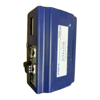
EC-BOS-6
AX
Mounting and Wiring Instructions
Revised: February 2008 Part Number: 05DI-HIBS6AX-10
About Expansion Options
About Option Cards
8
About Expansion Options
The EC-BOS-6
AX
provides for field-installable expansion with two kinds of options:
• Option cards—Install on connectors inside the EC-BOS-6
AX
base unit. See “About Option Cards” below.
• Accessory modules—To “chain” onto the EC-BOS-6
AX
’s 20-pin connector. See “About Accessory
Modules” below.
About Option Cards
The EC-BOS-6
AX
has two (2) option slots for custom option cards designed for use with the EC-BOS-6
AX
. Each
slot has a 30-pin connector on the EC-BOS-6
AX
base board. See Figure 2 on page 7.
Warning Power to the EC-BOS-6
AX
must be OFF when installing or removing option cards, or damage will
occur! Also, you must be very careful to plug an option card into its connector properly (pins
aligned).
Option cards typically provide additional communications features, such as the following available models
(with others still in development) listed below in Table 1.
Mounting Option Cards
For complete details, see the mounting & wiring instructions document that accompany the specific option card.
The following procedure provides a basic set of steps.
Procedure 2 Mounting option cards on a EC-BOS-6
AX
.
Step 1
Remove power from the EC-BOS-6
AX
—see the previous Warning.
Step 2
Remove the cover. See “Removing and Replacing the Cover,” page 7.
Step 3
Remove the battery and bracket assembly by taking out the four screws holding it in place, setting the
screws aside for later. Unplug the battery from the connector on the EC-BOS-6
AX
.
Step 4
Remove the blanking end plate for the slot you are installing the option card into.
(Retain the blanking plate in case the option card must be removed at a later date.)
Table 1 EC-BOS-6
AX
option cards.
Model
ModelModel
Model Description
DescriptionDescription
Description Notes
NotesNotes
Notes
EC-NPB-LON FTT-10A LON (LONWORKS
®
)
adapter with a 2-position
removable screw-terminal
connector plug.
Up to 2 LON option cards may be installed.
• If one LON option, it operates as LON1, regardless of slot.
• If two LON options, LON1 is Option slot 1, LON2 is Option slot 2.
EC-NPB-MDM 56Kbps Auto-dial/Auto-answer
Modem with one RJ-11 connector
for phone line.
Maximum of one. Does not have own UART. Must be installed in Option
Slot 1, where it operates as COM1. This disables the RS-232 base serial
port (DB-9 connector) on the EC-BOS-6
AX
during normal operation.
Note: If an EC-NPB-MDM is installed, and the “mode jumper” (see
Figure 2) is put in “Serial Shell” position, the EC-BOS-6
AX
base RS-232
port becomes active immediately following a reboot. This allows an
RS-232 connection to the “serial shell” for debugging purposes. To
re-enable the modem, you must put the mode jumper back in the “Normal”
position, and reboot again.
 Loading...