5
6
Primary Ethernet SEC (LAN1) “Link” (Green) and “Activity”
(Yellow).
7
(Behind Door) SHUTDOWN - Green, typically O.
If the “BEAT” LED stays illuminated constantly, does not light, or
blinks very fast, contact System Engineering for technical support.
Do not remove power from the controller during bootup or
during other critical operations, such as rmware upgrade to the
controller or any attached modules.
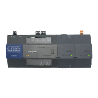
For more details on the controller LEDs and pushbutton switches, see
the EC-BOS-9 Mounting and Wiring Guide.
USB Ports & Switches, see image
8
Behind the front access door is one USB port, one pushbutton control,
and an associated LED.
1
SHUT DOWN - Recessed switch for controlled shutdown.
2
SHUT DOWN LED (Green) - Shut down “job in progress”
indicator.
3
DEBUG - USB-C port for serial debug communications.
e DEBUG port is a USB-C port for serial debug communications
to the controller only. Use a serial terminal program (for example,
PuTTY) to access the controller “system shell” menu. is provides
access to some basic platform settings.
Default DEBUG port settings are: 115200, 8, N, 1 (baud rate, data
bits, parity, stop bits). For details on using a serial connection to the
DEBUG port, see the EC-BOS-9 Install and Startup Guide.
NOTE: Login requires admin-level platform credentials.
Tab Mounting option, see images
i
DIN rail mounting is recommended. Where tab mounting is required,
use dimensions in the illustration to mount the controller and up to 4
option modules.
Caution: Do not mount hardware on both a DIN Rail and
with tab mounts to another surface. is causes physical stress on
equipment and prevents good connections between controller and
modules.
1
EC-BOS-9 controller with no option modules added. Allow at least
1.5” (38mm) clearance around all sides.
2
Option expansion module. Up to 4 may be used.
3
Note distances between center of tabs from one unit to another unit.
More Information
For more information see EC-BOS-9 Mounting and Wiring Guide.
WEEE (Waste of Electrical and Electronic
Equipment)
is symbol on our product shows a crossed-out “wheelie-bin” as
required by law regarding the Waste of Electrical and Electronic
Equipment (WEEE) disposal. is indicates your responsibility to
contribute in saving the environment by proper disposal of this Waste
i.e. Do not dispose of this product with your other wastes. To know
the right disposal mechanism please check the applicable law.
 Loading...
