1. TECHNICAL DATA
ARC B ARC 1BH ARC BH
Power supply 230 V~ / 50 Hz 24 V= 24 V=
Absorption 1,2 A 12 A 3 A
Torque 300 Nm 300 Nm 150 Nm
Run time 22 s/90° 15÷30 S/90° 15÷18 s/90°
Service class 3 - FREQUENT 4 - HEAVY DUTY 4 - HEAVY DUTY
Min. number of consecutive cycles 20 >50 >50
Intermittence S2 = 15 min, S3 = 25% S2 = 30 min, S3 = 50% S2 = 30 min, S3 = 50%
Temperature -20° C / +55° C -20° C / +55° C -20° C / +55° C
Degree of protection. IP54 IP54 IP54
Control panel E2 / Logic A21-A22 Logic C22 D2H / Logic C22-C22S
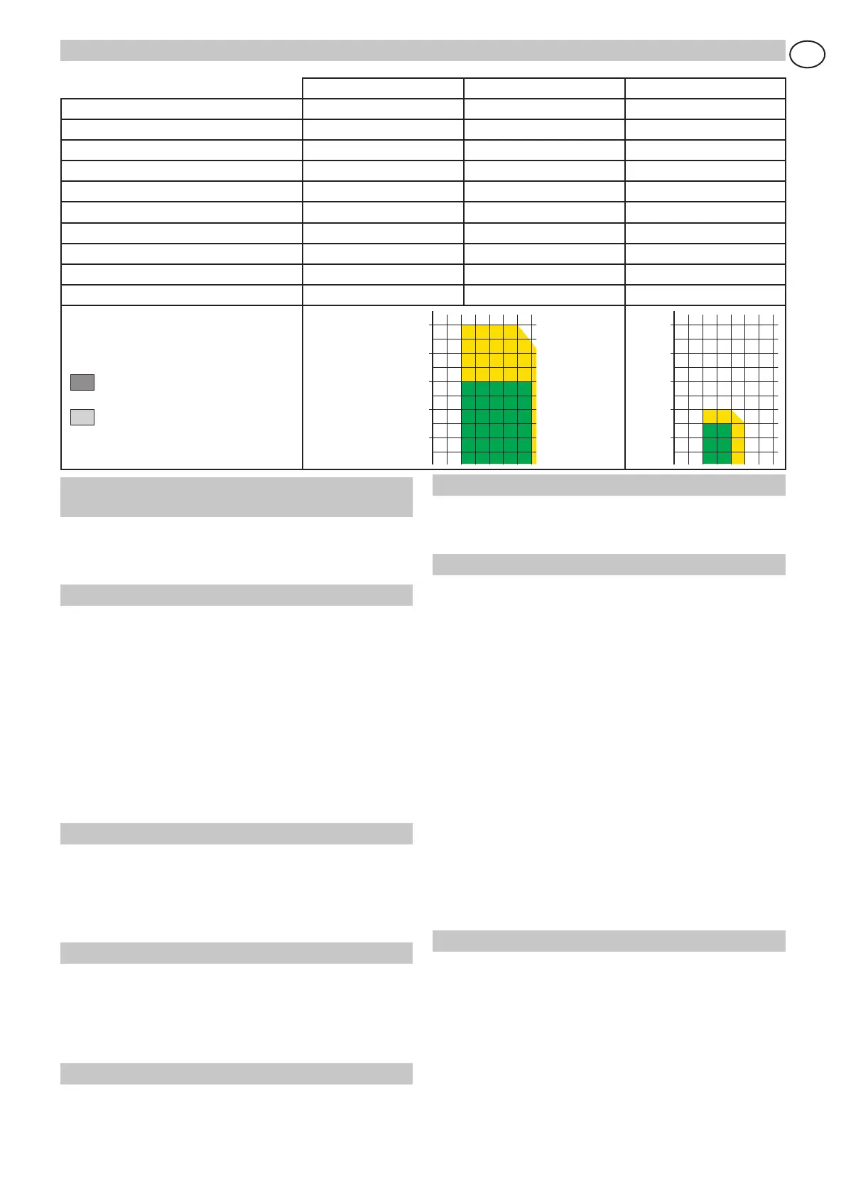
Application:
mm = door wing width
kg = door wing weight
Recommended dimensions
Limit dimensions
500 kg
400 kg
300 kg
200 kg
100 kg
m12345
500 kg
400 kg
300 kg
200 kg
100 kg
m12345
2. REFERENCE TO ILLUSTRATION and AC-
CESSORIES
The given operating and performance features can only be
guaranteed with the use of DITEC accessories and safety
devices.
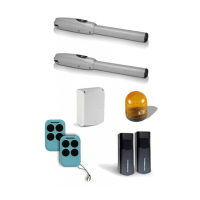
2.1 Standardinstallationreferences(g.1)
[1] Radio
[2] Flashing light
[3] Key selector
[4] Connect power supply to a type-approved omnipolar-
switch with a contact opening gap of no less that
3 mm (not supplied by us) protected against accidental
and unauthorized activation. Connection to supply mains
must be carried out in an independent raceway separate
from control connections and safety device connections.
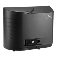
[5] Control panel
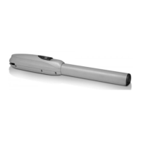
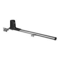
[6] Arc B geared motor
[7] Photocells
2.2 Geared motor references
[8] Gate attachment bracket
[9] Housing
[10] Attachment plate
[11] Drilling templates for release key
[12] Release shaft
2.3 Accessories
ArcFB(*) Adjustable stop
ArcPL(*) Plate for front attachment of geared motor
Box FC1 Limit switch
(*) Two TCEI M8x130 screws, don’t supply by us, are necessary in
order to use the ArcFB and ArcPL accessories at the same time.
3. INSTALLATION
Unless otherwise specied, all measurements are expressed
in millimetres.
3.1 Preliminary checks
Check that the structure is sufciently sturdy and that the hinge
pivots are properly lubricated. Provide an opening and closing
stop.
3.2 Geared motor installation
- Remove the geared motor from its package. Attention:
Cover [9] is not secured.
- Disassemble the reduction gear from the fixing plate [10].
- Attach plate to gate column according to measurements
specified in figures 6 and 7, depending on type of installation.
- Assemble the geared motor on the fixing plate following
fig. 8 for the fitting onto the left pier, inside view, and fig.
9 for fitting onto the right pier, inside view.
- Release the geared motor (see operating instruction).
- Attach articulated arms and gate attachment bracket as
shown in figures 10 and 11 and according to measure-
ments specified in figures 6 and 7.
Attention: bring the leaf to the stop line, align the arms
by means of holes [D] as shown in the detail in fig. 10.
The articulations on the arms should be lubricated and
the screws tightened in such a way as not to block arm
movement.
- Drill the cover Ø 14 near release shaft [12] (there are two
drilling templates [11] in side the cover) and insert the
rubber plug (supplied). Attach the cover to the geared
motor.
4. ELECTRICAL CONNECTION
- ARC B geared motor electrical wiring and starting are
shown in fig. 12 and in the installation manual of Control
Panel E2, Logic A21 and LogicA22. To reverse the direc-
tion of rotation, exchange the motor phases (U with V
and/or X with Y).
- ARC 1BH geared motor electrical wiring and starting
are shown in fig. 15 (1 wing) or in fig. 16 (2 wings) and
in the installation manual of Control Panel LogicC22. To
reverse the direction of rotation, exchange the motor
phases (36 with 34 and/or 33 with 31).