dIXEL
Operating Instructions
cod. 1592017410
1592017410 XLH360 GB r1.0 15.04.2005.doc XLH360 15/16
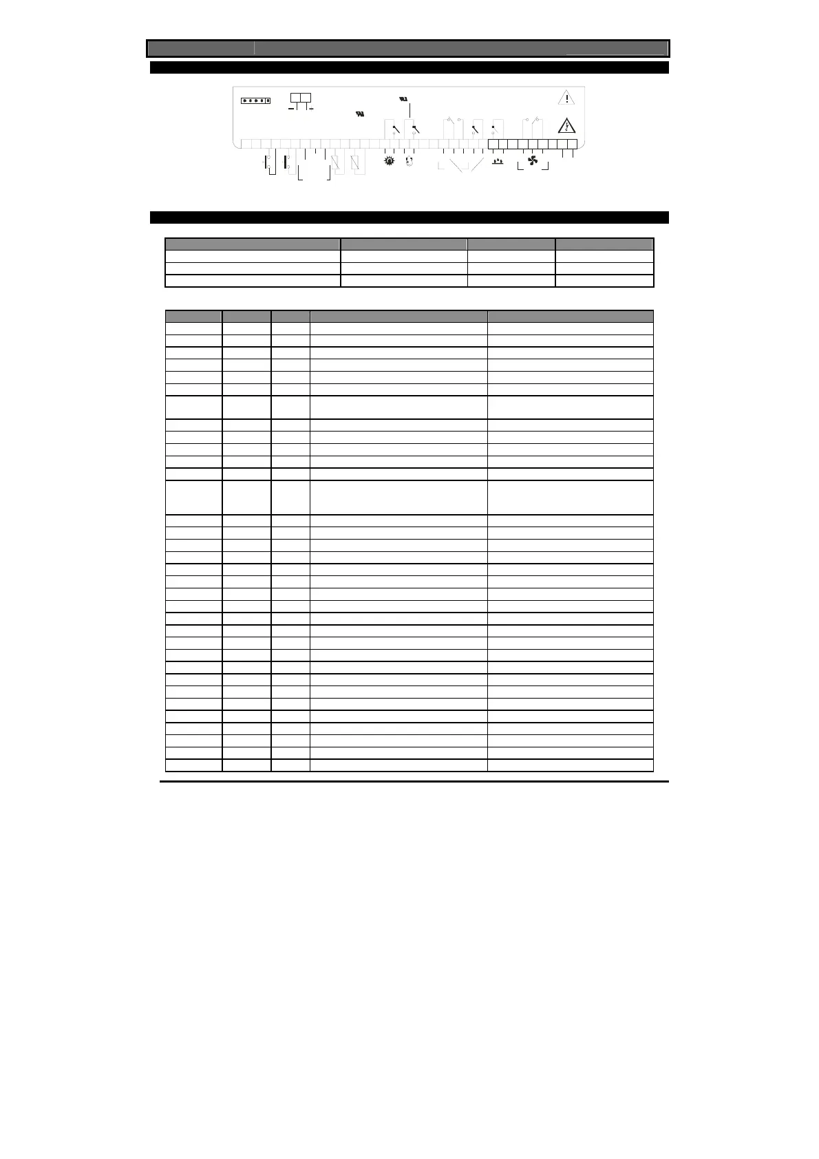
16. XLH360 WIRING CONNECTIONS
1234567 891011121314 151 6 17 18 19 20 21 222 3 24 25 26 2728 29 30 31 33 34
Conf. Do o r
Ro om
Evap.
HO T K E Y
16A
250V~
16A
250V~
8A
250V~
20 A 2 50 V
16 FLA (96L RA)
20A 250V
16 F LA (9 6LRA)
8A
2 50V
~
Supply
120/230V~
NLine
NC
Fa n
35 36
In
12 V § gnd
Input
4÷20mA
NC
Def
Extr.
Heater Hum
Light
De-
Hu m
Co mp
RS 48 5
110 Vac Power Supply: connect to 33-34 terminals
17. DEFAULT SETTING VALUES
Set temperature Set humidity Duration
Dripping Phase 5.0 °C - - 5.00 h
Running Phase 5.0 °C 50.0 RH% 5.00 h
Stopping Phase - - 5.00 h
Label Value Menu Description Range
dbt
2.0 Pr1 Half dead band width for temperature 0.1°C o 1°F ÷ 25°C o 77°F
dbH
5.0 Pr1 Half dead band width for humidity 0.5 ÷ 50
LS
-40.0 Pr2 Minimum temperature set point limit -50.0°C o –58°F ÷ Set T
uS
110 Pr2 Maximum temperature set point limit Set T ÷ 110°C o 230°F
odS
1 Pr2 Outputs activation delay at start up 0 ÷ 250 min
Ac
1 Pr1 Anti-short cycle delay 0 ÷ 30 min
tHu c-H Pr2 Humidity regulation
db = dehumidifier relay.; cHu = dehum+
compr.; c-H= without dehum. relay
LSH
0.0 Pr2 Minimum humidity set point limit Lci ÷ Set H
uSH
100 Pr2 Maximum humidity set point limit Set H ÷ uci
cF
°C Pr2 Measurement unit °C ÷°F
rES
dE Pr2 Resolution (for °C): in = integer / dE = decimal
rEH
Hd Pr2 Resolution for RH%: in = integer / Hd = half digit
trC
co Pr2 Instrument behaviour at the end of the cycle
co=start holding, in=stop regulation,
cL=restart the first phase+End message; cLE
= restart the first phase
tdF
rE Pr2 Defrost type rE, rT, in
EdF
in Pr2 Defrost mode In, Sd
SdF
0.0 Pr2 Set point for SMART DEFROST -30 ÷ +30°C / -22÷+86°F
dtE
8.0 Pr2 Defrost termination temperature -50,0÷110°C/ -58÷230°F
idF
6 Pr1 Interval between defrosts 1 ÷ 120 h
MdF
20 Pr1 Duration of defrost 0 ÷ 250 min
dFd
it Pr2 Display during defrost rt / it / SEt / dEF / dEG
dAd
30 Pr2 Defrost display time out 0 ÷ 250 min
Fdt
0 Pr2 Draining time 0÷60 min.
dPo
no Pr2 First defrost after start up n ÷ y
Hud
no Pr2 Humidity control during defrost no; yES
Fnc
c-n Pr2 Fan operating mode c-n / c-Y / o-n / o-Y
rFi
0 Pr2 Interval between 2 cycles of change of air 1 ÷ 120 h (0 = manual start)
rFd
0 Pr2 Duration of cycle of change of air 1 ÷ 250 min (0 = manual stop)
ALc
Ab Pr2 Temperature alarm configuration rE = relative / Ab = absolute
ALL
-40.0 Pr1 Low temperature alarm setting 0°C ÷ 50.0°C / -50.0°C ÷ ALu
ALu
110 Pr1 High temperature alarm setting 0°C ÷ 50.0°C / ALL ÷ 110°C
ALH
1.0 Pr2 Temperature alarm recovery differential 0.1°C o 1°F ÷ 25°C o 77°F
ALd
15 Pr2 Temperature alarm delay 0 ÷ 250 min
dAo
1.3 Pr2 Delay of temperature alarm at start-up 0.0 ÷ 23.5 h
EdA
20 Pr2 Alarm delay at the end of defrost 0 ÷ 250 min
 Loading...