Universal-XR 12/17 UXR01212015_REV1.4mm
Installation and Operating Instructions
12. EVAPORATOR FAN CONTROL (only when parameter tC = 6 or 7)
The fan control mode is selected by means of the “FnC” parameter:
Fans will cycle ON and OFF with the compressor and be off during defrost cycle.
Fans will run continuously, but be off during defrost cycle.
Will switch ON and OFF with the compressor and be on during defrost cycle (*).
Fans will run continuously and be on during defrost cycle (*).
(*) Note: Fans will stop if the temperature value set in parameter “FSt” is exceeded.
Parameter FSt sets the fan stop temperature. This is the maximum temperature, detected by the evaporator probe, above which the evaporator fans
will stop.
Leave FSt above ambient temperature during commissioning to avoid fan short cycle.
After finishing the defrost phase, there is a stand still drain time, set by parameter Fdt. When this period has expired, the refrigeration cycle
commence but the evaporator fans remain off until Fnd (fan delay) times out.
13. SPECIAL APPLICATIONS – DEAD BAND CONTROL
13.1 DEAD BAND CONTROL (COOLING & HEATING) tc=7
With [oAb = db], the compressor relay controls cooling as normal but the 3rd (auxiliary/ fan) relay is used to control a heater. The value entered in
parameter HY will now be set equal on both sides of the SET POINT. Example: if [HY = 1°C] that will create a 2°C Dead Band.
At [SET POINT + HY], cooling switches on. At [SET POINT – HY], heating switches on. Either cooling or heating switch off when temperature returns
to SET POINT.
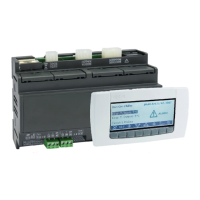
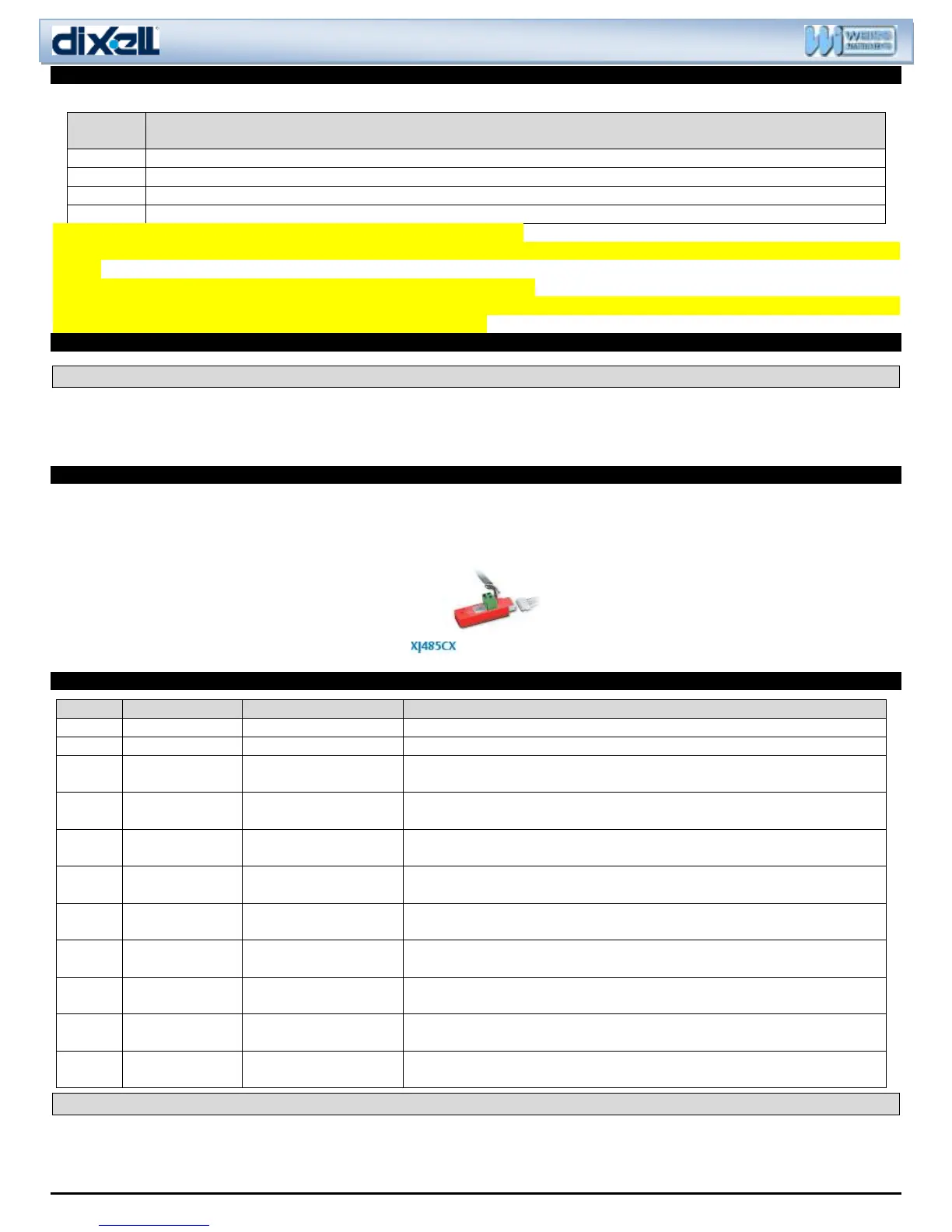
14. COMMUNICATIONS WITH XWEB or OTHER MONITORING SYSTEMS
Using the XJ485CX-00000 it is possible to network the Universal XR60CX to the XWEB monitoring systems, or a third-party system. The controller
has TTL communications that can be converted with the XJ485CX key. The key is connected to the control via the HOT KEY port, with a small 5 wire
cable. It is then possible to set a unique address via the “Adr” parameter. Then using a two-wire communications daisy chain the controls can be
monitored.
15. ALARMS
Alarm output ON; Other outputs unchanged.
Alarm output ON; Compressor output according to parameters Con and CoF.
Alternating with
room temperature
Alarm output ON; Other outputs unchanged; End defrost is timed.
Alternating with
room temperature
Second evaporator probe
failure
Alarm output ON; Other outputs unchanged; End defrost is timed.
Alternating with
room temperature
Alarm output ON; Other outputs unchanged.
Alternating with
room temperature
Minimum temperature
alarm
Alarm output ON; Other outputs unchanged.
Alternating with
room temperature
Alarm output ON; Other outputs unchanged.
Alternating with
room temperature
Alarm output ON; Other outputs unchanged.
Alternating with
room temperature
Alarm output ON: Outputs re-start if parameter rrd = 1.
Alternating with
room temperature
Alarm output ON; Other outputs unchanged.
Alternating with
room temperature
Alarm output ON; Other outputs OFF.
15.1 MUTING ALARM BUZZER & RELAY
The alarm buzzer can be muted, by pressing any button. The controller will briefly show the reset “rES” label. Parameter tbA defines how the alarm
relay will respond to the muting of the buzzer.

 Loading...