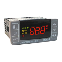
Universal-XR 6/17 UXR01212015_REV1.4mm
Installation and Operating Instructions
5. PARAMETERS, FUNCTIONS IN DETAIL
Table 4: controller parameters in detail
Type of Controller: tells the Universal-XR which type of controller it will be operating as.
1 = on/off Heating thermostat – 1 relay & 1 probe;
2 = Combined thermostat with off cycle defrost timer – 1 relay & 1 probe;
3 = Combined thermostat with time initiated & time terminated defrost – 2 relays & 2 probe;
4 = Combined thermostat with time initiated & temperature terminated defrost – 2 relays & 2 probes; alarm
5 = Combined thermostat with time initiated, temperature terminated defrost + 2 relays & 2 probes; defrost
6 = Combined thermostat with time initiated, temperatures terminated defrost + evaporator fans control with delay after defrost – 3 relays & 3 probes;
7 = Combined thermostat with time initiated, temperatures terminated defrost + evaporator fans control with delay after defrost – 3 relays & 3 probes. Fully open map
Probe Type: configures the controller to work with PTC or NTC probes.
0= ptC = PTC,
1= ntC = NTC.
Differential: (1 to 50) sets the degrees above Set Point at which the compressor cuts in.
Note: when tC = 1 (heating applications) the tC value is automatically set below the Set Point. If the temperature decreases and reaches set point minus differential the regulation
output is activated and then turned off when the temperature reaches the set point value again.
Minimum set point limit: (-55°C to SET or -67°F to SET) sets the lower limit of set point adjustment.
Maximum set point limit: (SET to 150°C or SET to 302°F) sets the upper limit of set point adjustment.
Anti-short cycle delay: (0 to 50min) minimum interval between the compressor stop and the next possible restart.
Second compressor start delay: (0 to 255sec)
Probe selection for temperature alarms
0=P1, Room Probe
1=P2, Evaporator Probe
2=P3, Display Probe
3=P4, Hot Key Connector Probe, Condenser Alarm Probe
Temperature alarm configuration:
rE = Related to Set Point;
Ab = Absolute.
Note: Relative means alarms are linked to the Set Point and will follow it if it is adjusted. In this case ALU & ALL set the temp over & under Set Point for alarm. Absolute means
ALU & ALL are fixed alarm temperatures, which are not affected by any Set Point adjustment.
High temperature alarm:
ALC = rE→ [0 to 50°C] or [0 to 90°F];
ALC = Ab → [ALL to 150°C] or [ALL to 302°F].
Low temperature alarm:
ALC = rE → [0 to 50°C] or [0 to 90°F];
ALC = Ab → [-55°C to ALU] or [-67 to ALU].
Differential for alarm recovery, the control will still display the alarm until this value+
Temperature alarm delay: (0 to 255min) time interval between an alarm condition occurring and the alarm is signalling.
Delay of temperature alarm at start-up: (from 0 to 720min; res. 10min) time delay of any temperature alarm during pull down following “power on”.
Outputs activation delay at start up: (0 to 255min) time delay before any output relay activates following “power on”.
Thermostat override: (0 to 990min; res. 10min) period during which the compressor will run continuously, regardless of temperature. Setting this parameter to 0 disables this
function.
Set point for continuous cycle: (-55 to 150 °C or -67 to 302°F) it sets the set point used during the continuous cycle.
Defrost delay after fast freezing: (0 to 255min) time interval between the end of the thermostat override period and the start of the following defrost related to it.
Interval between defrosts: (0 to 255hours) time interval between the beginning of two consecutive defrosts.

 Loading...