8
©
2016 DJI All Rights Reserved.
MATRICE 600
User Manual
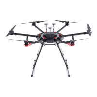
7. Connect the power cables to the center frame. Each cable must be screwed into a positive (+) or
negative (-) gold bracket. Red cables are positive and black cables are negative. Each bracket will
have two cables of the same color screwed into it. Then tighten each M3×5.5 screw (square head)
using the square socket wrench.
8. Plug each ESC signal cable into the slot near each arm on the center frame.
9. Ensure that all ESC cables and power cables are correctly installed on the center frame.
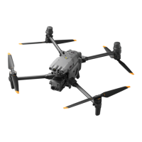
10. Identify the position and rotational direction of the motors. When viewed from above, motors M1 to
M6 are arranged counter-clockwise with motors M1 and M2 at the front of the aircraft and motors
M5 and M6 at the rear. Motors M1, M3 and M5 rotate counter-clockwise as indicated by the “CCW”
mark, while motors M2, M4 and M6 rotate clockwise as indicated by the “CW” mark.
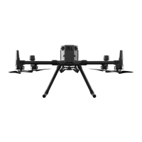
Mounting the Retractable Modules
DO NOT mix up the mounting positions for the left and right retractable modules. Identify
the left module by locating the control board and power cable integrated on the left module.
Operate with care to avoid injury from the connecting arm.
Power Cables
ESC Signal Cable
M1M2
M3 M6
M4
M5

 Loading...