接电调
接云台
R/C Receiver
(JR)
RUDD
THRO
AILE
ELEV
3-position switch channel
R/C Receiver
(Futaba / Hitec)
1
2
3
4
Futaba S-Bus
S-Bus
F1
F2
Aircraft Nose
PPM
PPM
ESC
M1
M2
M3
M4
M5
M6
R/C System
These are example connections.
Please setup Aileron, Elevator,
Throttle, Rudder channels on your
TX f irst, and c hoose one 3 -
positions switch/channel as control
mode switch, then connect your
receiver to the right ports on MC.
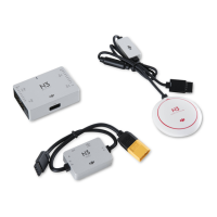
VU
· Do not mount it on any other electronic devices. Make sure You
can see the LED light during the flight.
· If use with DJI multi-rotor, you can solder the VU power cable to
power pads on frame bottom board. Please refer to DJI multi-rotor
manual for details.
· If use with 3
rd
part multi-rotor, you can make a connecter by
yourself to connect VU, ESCs and battery.
· Sufficient air flow over the VU is highly recommended.
ESCs, Motors
· Motors and ESCs in DJI multi-rotor kit are recommended.
· Please make sure you are using the ESCs and motors
recommended by the manufacturer of your multi rotor first. NAZA
output is 400Hz refresh frequency.
· If you use 3
rd
party ESCs, please make sure the ESCs travel
midpoint is at 1520us. DO NOT use 700us travel midpoint ESC,
as it may lead aircraft to fly away or cause injury and damage.
After connect ESCs to motors, calibrate all your ESCs one by one
through the receiver directly before connect them to your MC,
Make sure program all of them into Governor off, Break off and
Normal Start up to get best experience.
Pitch
Roll
MC
· Please use 3M gummed paper provided To mount MC, and mount
MC parallel to the aircraft horizon.
· The output ports of MC (the right side in figure) should point to
the front of multi-rotor. You’d better put MC at the gravity
center of multi-rotor. Please make sure all ports are accessible
when installing the MC so as to facilitate wiring and software
configuration.
· In three-pin ports, pins near the nicks are signal pins.
· After choosing a location to mount the MC, it is
· recommended that you DO NOT mount the MC
· until all wirings and software configurations are completed.
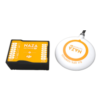
(Optional) GPS/COMPASS
· GPS/Compass is sensitive to magnetic interference, should be far away from any electronic devices.
· You should use epoxy resin AB glue to assemble the GPS bracket first as the figure showed in
previous page.
· Mount the bracket on the center plate of craft first, then fix the GPS on the plate of the bracket (by
3M glue provided). The GPS is sensitive to vibration interference, so position the bracket at least 10
cm from any rotor.
· The DJI logo marked on the GPS should face the sky, with the orientation arrow pointing directly
forward. The GPS/Compass is packaged with a special indication line for mounting for the first time.
· If you are uncertain whether materials near the GPS/Compass module are magnetic or not, you can
use a compass or magnet to check it. If you use your own mounting rod, make sure it is NOT
magnetic!
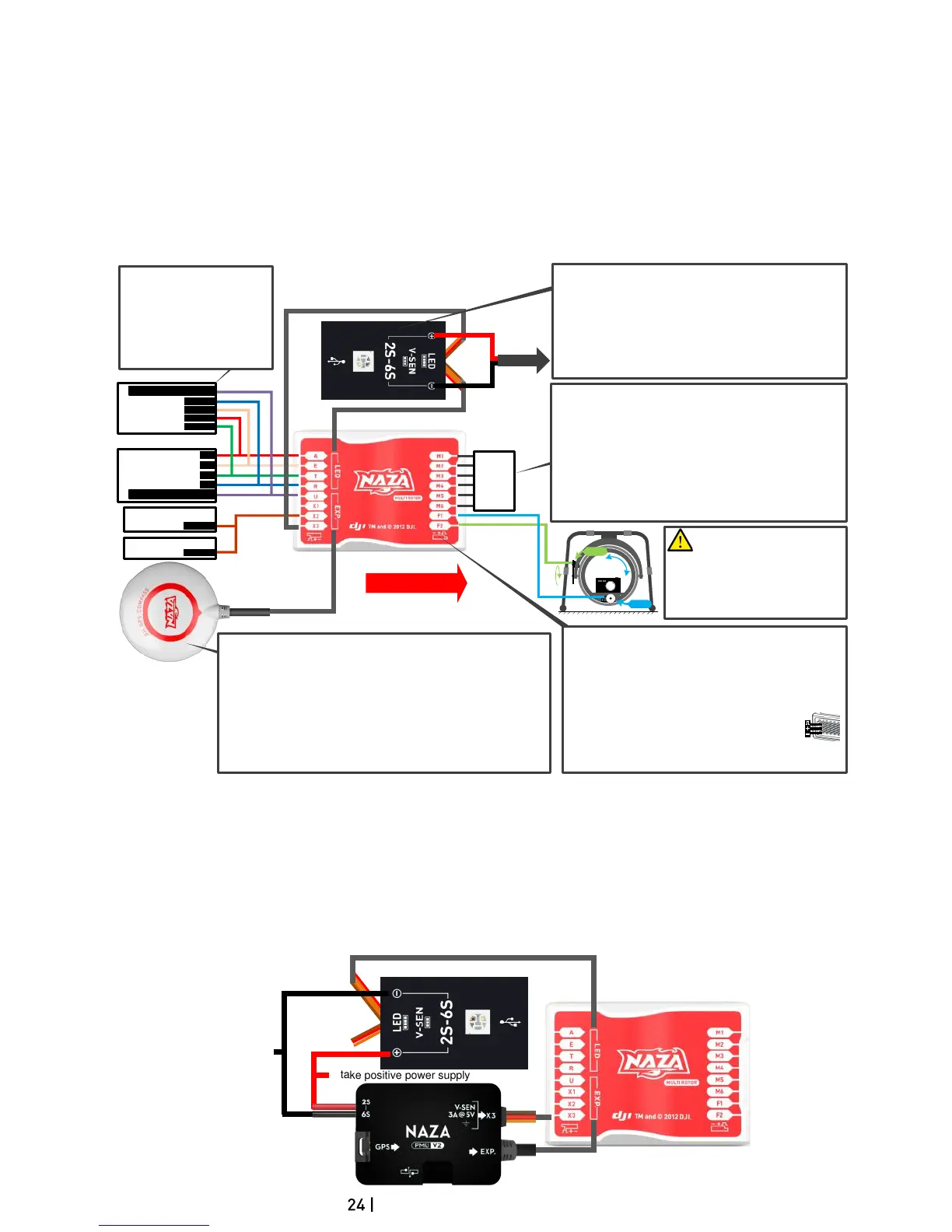
3-position switch channel
TO Battery
Important: the continuous
output of the VU is 3A@5V, and
the maximum instant current is 7.5A. If
the V U cannot afford the working
current for your servos, please use an
independent power supply; otherwise,
it may cause the V U safeguard and
lead to the main controller reboot.
 Loading...