7
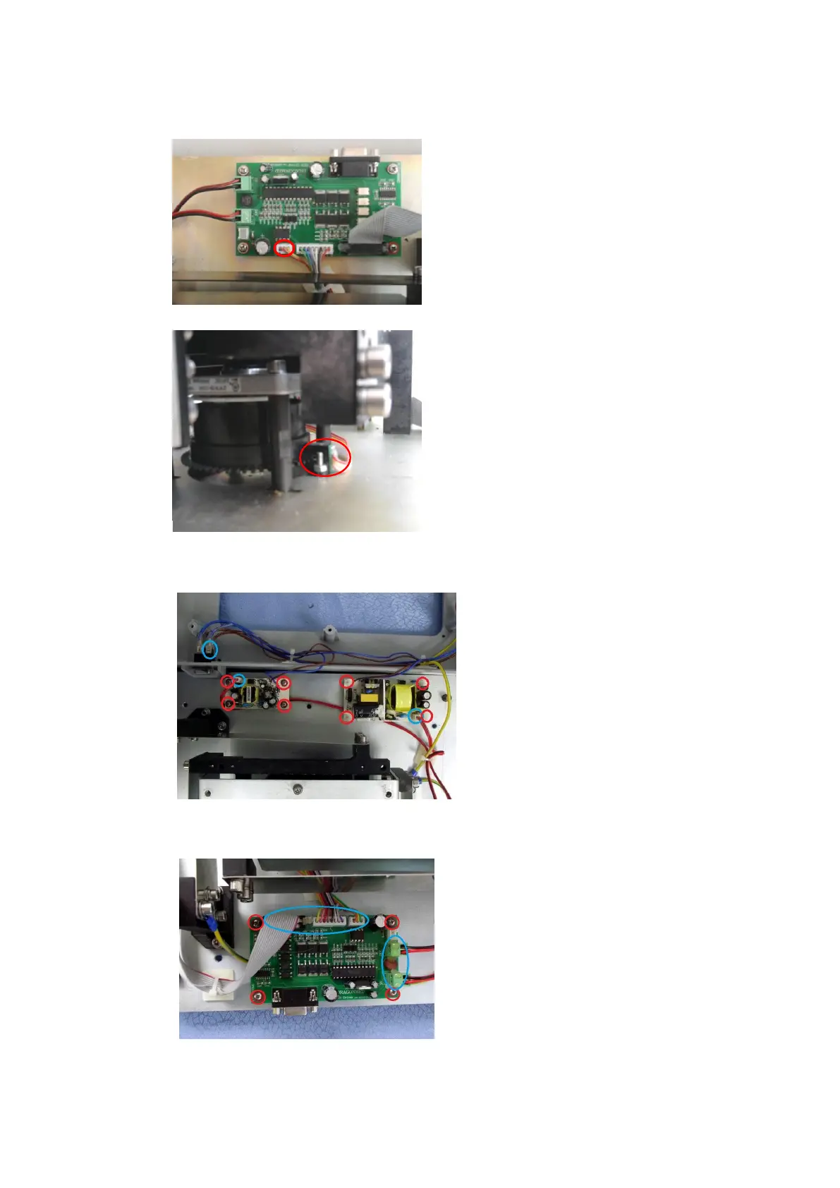
2.5 Replacement of photoelectronic switch
Step 1:
Unplug the cable marked by red
circles on MS-Motro Board, as shown
in figure;
Step 2:
When you replaced new
photoelectronic switch, the Shaft
Encoder on the motor must match
with photoelectronic switch. When
motor is turning, Shaft Encoder
cannot be frictional contact with
Photoelectronic. After Shaft Encoder
is in place, lock it with screws.
2.6 Replacement of power board component
As shown in the left figure, unplug
the connector marked by blue
circles, remove the 8 screws marked
by red circle and keep them well,
then replace new power board
component.
2.7 Replacement of motor drive board
As shown in the left figure, unplug
connectors marked by blue circles,
remove the 4 screws marked by red
circles and keep them well, then
replace a new motor drive board.