1164/1164NS Series Installation and Programming Guide 8
ENABLE THE TAMPER SWITCH (OPTIONAL)
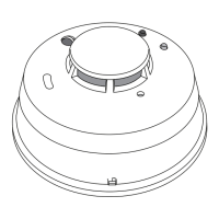
The 1164 features a tamper switch to send a trouble message to the panel if the
detector is removed from the mounting base. To enable the tamper switch, follow the
directions below:
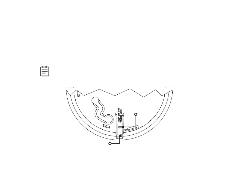
1. Identify the small plastic tab that’s located on the mounting base.
See Figure 4.
2. Cut the tab o of the base. The tamper switch will take eect after the
detector is installed.
Note: After the tamper switch is enabled, a small screwdriver must be
used to depress the cover latch before the detector can be removed from
the base.
2
Locking Tab
Cover Latch
Figure 4: Mounting Base and Tamper Switch