ADD A USER CODE WITH CARD
1. Enter the USER MENU and go to USER CODES?
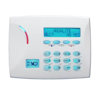
2. Press a top-row select area to add a USER CODE
3. Select ADD
4. Select the USER NUMBER and press CMD
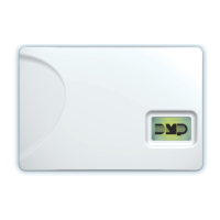
5. Scan card by waving it over the blue status LED
6. Press a top-row select area and add a USER NAME
and press CMD
7. Press a top-row select area and enter 11 to assign
PROFILE 11 to this user.
8. Press CMD until USER ADDED displays
CREATE AN OUTPUT SCHEDULE
1. Re-enter the schedule programming section. Press
CMD and select OUTPUT.
2. Enter output 1, then schedule 2.
3. Press the BACK ARROW to exit schedule
programming.
4. Advance panel TIME to test the BEGIN and END times
for the schedule.
ADD A 734 INTERFACE MODULE
1. Connect the 734 module to the KEYPAD BUS
2. Use the dip switches on the 734 to address the
module
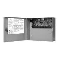
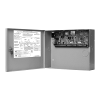
3. Reset the panel and enter 6653 (PROG) to enter the
panel programmer
4. Using CMD, navigate to DEVICE SETUP
5. Program the 734 at the same address set with the dip
switches
6. Press a top-row select area to name the device
7. Press a top-row select area to program the DEVICE
TYPE as a DOOR
8. Assign ACCESS AREA 2
9. Set PUBLIC DOOR, FIRE EXIT, and DOOR REAL-TIME
STATUS to YES
10. Connect the reader to TERMINALS 1–4 on the 734
11. Connect the POSITIVE terminal on the external power
supply to the C (Common) terminal on the 734
12. Connect the NEGATIVE terminal on the door strike to
the NEGATIVE terminal on the external power supply
13. Connect the POSITIVE terminal on the door strike to
the NO (Normally Open) terminal on the 734
14. Install the Model 333 Suppressor between the C and
NO terminals on the 734
ADD A 734N/734N-POE
The 734N and 734N-POE only have one dierence and
that is how they are powered. To program a 734N/734N-
POE, programming needs to take place in two places: the
panel and the 734N/734N-POE.
PANEL PROGRAMMING
1. Reset the panel and enter 6653 (PROG) to enter the
panel programmer
2. Using CMD, navigate to NETWORK OPTIONS
3. Write down the PANEL IP ADDRESS
4. Write down the 734N LISTEN PORT and make sure it
is open to the local network
5. Press a top-row select area to set the 734N
PASSPHRASE
6. Using CMD, navigate to DEVICE SETUP
7. Program a DEVICE NUMBER for the 734N
ê For AX-Bus use, the 734N must be at least v101 (10/21/16)
8. Press a top-row select area to name the device
9. Assign ACCESS AREA 2 to the device
10. Set PUBLIC DOOR, FIRE EXIT, and DOOR REAL-TIME
STATUS to YES
WIRING/734N PROGRAMMING
1. Connect the 734N to the local network
ê For 734N-POE connect network cable to a POE switch
2. Connect the reader to TERMINALS 1-4
3. Connect DC power
ê The 734N accepts 12-24VDC power input
4. Plug a keypad into the PROG header on the 734N
ê The keypad should be Address 1 with supervision turned on
5. Press CMD to navigate to 734N COMMUNICATION
and press a top-row select key
6. Program the DEVICE NUMBER for the 734N
ê This should match the device that was created in the panel
7. If entering STATIC IP information, set DHCP to NO,
otherwise, press CMD
ê The 734N requires an IP, subnet mask, and gateway address for static network
programming
8. Enter the PANEL IP PORT
ê This should match the 734N Listen Port from the panels’ programming
9. Enter the 734N PASSPHRASE that was entered in the
panel
10. Program access options for this door
11. Using CMD, advance to STOP and press a top-row
select key to save programming
12. Remove the keypad from the PROG header
13. Connect the POSITIVE terminal on the external power
supply to the C (Common) terminal on the 734N
14. Connect the NEGATIVE terminal on the door strike to
the NEGATIVE terminal on the external power supply
15. Connect the POSITIVE terminal on the door strike to
the NO (Normally Open) terminal on the 734N
16. Install the Model 333 Suppressor between the C and
NO terminals on the 734N
ADD A CUSTOM CARD FORMAT
PANEL PROGRAMMING
1. Reset the panel and enter 6653 (PROG) to enter the
 Loading...

