36 DoAl.L INSTRUCTION MANUAL
Misalignment of the weld is usually caused
by
worn
or dirty jaws. However,
if
the welder
jaw inserts and clamps
are
clean and
not
worn
and the welds
are
out
of line, the jaws
'
are
not
aligned properly. This misalignment
can
bevdeterminecl by inspecting the weld
after the flash has been removed. After
determining which jaw is
not
in alignment,
the jaws
can
be adjusted
as
desired. The
movable jaw
can
be moved up
or
down in
a
vertical
are
by adjusting the Allen-type
set-screws in the
rear
of the jaw. These
set-.
screws
also position button bearings in back
of the movable jaw,
so
that
if
the position
of the jaw is moved,
care
must
be taken
that the bearings
are
not
set
up
too
tight.
If
the position of the stationary jaw is
changed, make certain that the gap between
the jaws is 3/16" in the open position.
Never file the silver
Contact
points. The
silver oxide which forms when the points
burn is
an
excellent conductor.
When the grinding wheel has become
badly grooved from squaring of
saw
ends,
it
should be removed and reversed.
In
this
way
full
use
of the wheel
can
be made before
replacement becomes necessary.
HYDRAULIC SYSTEM
Keep oil level in the tank
to
the full mark
on
dipstick
at
all times. Drain and clean tank
and oil filter every six months. The complete
tank
can
be removed from the machine by
removing
one
bolt holding
it
to
the base.
The oil filter
screen
is inside the tank attached
to
the outlet connection
on
the cleanout
plate.
'
'
If
the hydraulic pressure drops, dirt may
be lodged in the relief valve
or
the relief
valve spring may need replacing. The relief
valve is located above the oil pump
on
the
drive
motor
base. This valve is
set
at
the
factory for 200 lbs. pressure. I1-L
rare
cases
it
may be necessary
to
increase the pressure.
To do this,
remove
the cap and
turn
the
adjustment
screw
clockwise. Use
a
pressure
gauge when adjusting this pressure.
An
out-
let is provided immediately below the relief
valve for this purpose. Do
not
set
the pressure
above 250 lbs. under any circumstances.
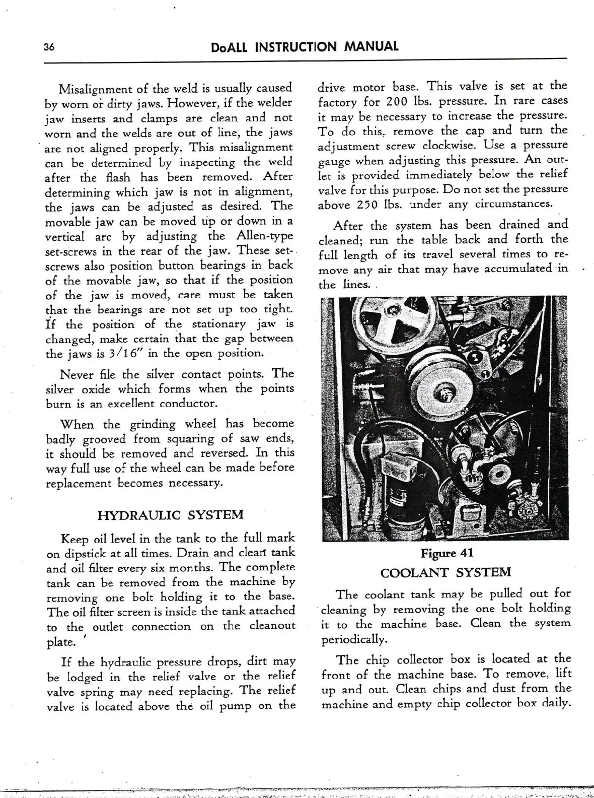
After the system has been drained and
cleaned;
run
the table back and forth the
full
length of its travel several times
to
re-
move
any air that may have accumulatedin
the lines.
.
Fe41
COOLANT SYSTEM
The coolant tank may be pulled
out
for
cleaning by removing the
one
bolt holding
it
to
the machine base. Clean the system
periodically.
The chip collector box is located
at
the
front of the machine base. To
remove,
lift
up and
out.
Clean chips and dust from the
machine and empty chip collector box daily.