24 Dolby
®
Digital Cinema System Manual Issue 0.92 (Preliminary)
Installing a Dolby Digital Cinema System
3.3.10 Assembling and Wiring the RJ45/DB25 Adapter
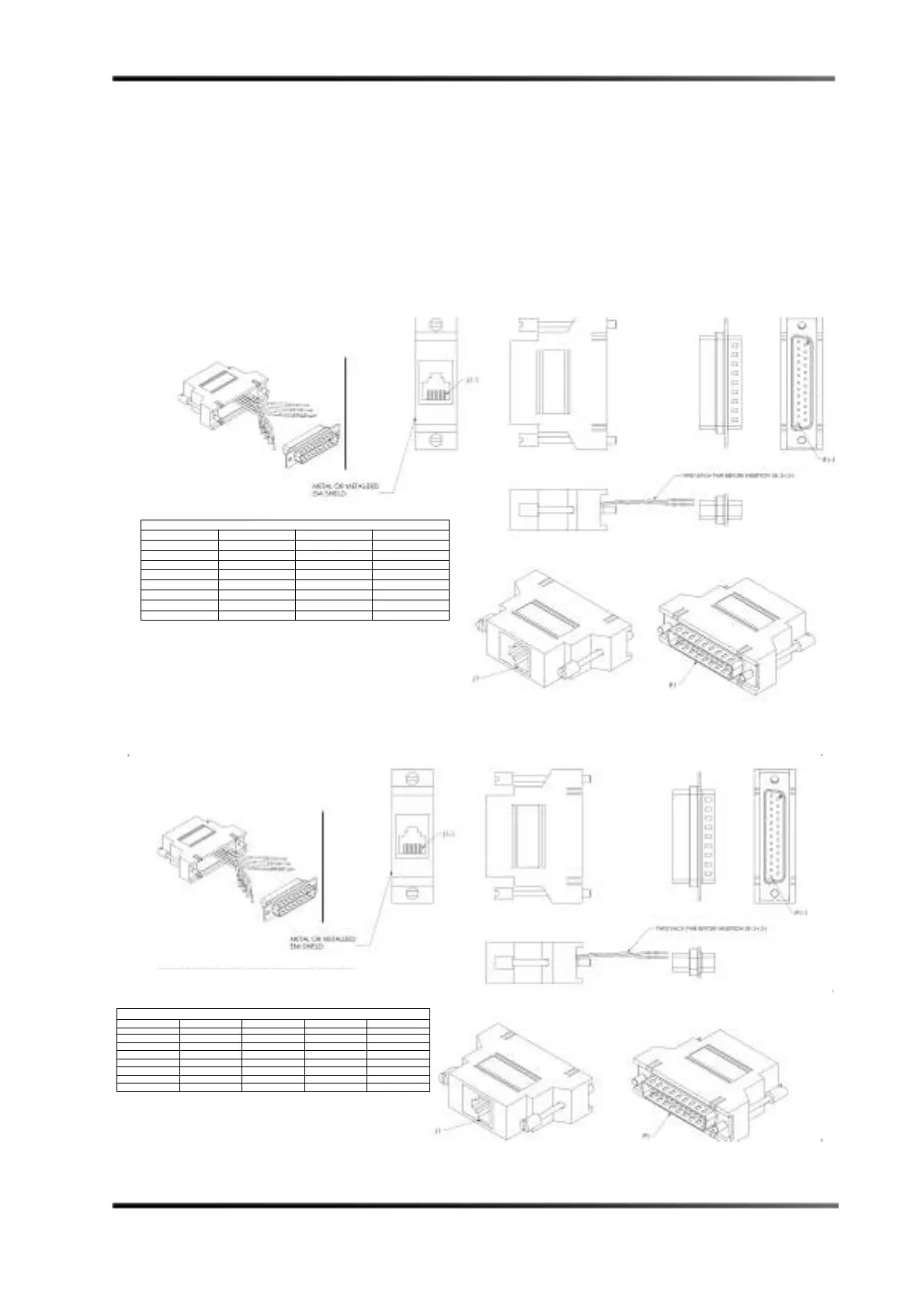
To assemble and wire-up the RJ/45/DB25 adapter:
1. Use the wiring diagram for your configuration (Figure 3-11 for a DMA8Plus or CP750
or Figure 3-12 for a CP650), then insert (snap) the pre-wired contacts into the DB25
(P1) housing, and secure the two pieces.
2. Attach a label (25 inches x 9 inches) in the area shown in the wiring diagram (e.g.,
DB25 to 4xAES input or DB25 to Option I/O input).
3. If a drain wire is provided, attach it to the DSUB housing.
Figure 3- 11
Figure 3-11 Assembling and Wiring the RJ45/DB25 Adapter (DMA8Plus or CP750)
Figure 3- 12
Figure 3-12 Assembling and Wiring the RJ45/DB25 Adapter (CP650 Configuration)
WIRING DIAGRAM
AES PAIR FROM COLOR TO
1+ (CH 1/2+) J1-1 BLUE P1-14
1- (CH 1/2-) J1-2 ORANGE P1-2
2+ (CH 3/4+) J1-3 BLACK P1-3
3+ (CH 5/6+) J1-4 RED P1-17
3- (CH5/6-) J1-5 GREEN P1-5
2- (CH 3/4-) J1-6 YELLOW P1-16
4+ (CH7/8+) J1-7 BROWN P1-6
4- (CH 7/8-) J1-8 WHITE P1-19
*FOR A TYPICAL CP650 OPTION CARD I/O WITH A CAT790
ALL AES PAIR - WIRES MUST BE SOLDERED TO PIN 7.
WIRING DIAGRAM
AES PAIR FROM COLOR TO Cat778 I/O TO Cat790 I/O
1+ (CH 1/2+) J1-1 BLUE P1-1 P1-1
1- (CH 1/2-) J1-2 ORANGE P1-2 P1-7*
2+ (CH 3/4+) J1-3 BLACK P1-4 P1-2
3+ (CH 5/6+) J1-4 RED P1-3 P1-13
3- (CH5/6-) J1-5 GREEN P1-13 P1-7*
2- (CH 3/4-) J1-6 YELLOW P1-12 P1-7*
4+ (CH7/8+) J1-7 BROWN P1-5 P1-21
4- (CH 7/8-) J1-8 WHITE P1-20 P1-7*
 Loading...