ENiQ® Wall Readers & Terminals
____________________________________________________________________________________
19
Option 3: External voltage source supplies the DOM device
If you operate the DOM device with an external power source (12 V – 24 V DC), connect
the positive pole to terminal 7 and the negative pole to terminal 8. This must also be
done with an external voltage source at the Passive Reader (HiSec). (The data between
the controller and the Passive Reader are still exchanged via terminals 18, 19 and 20).
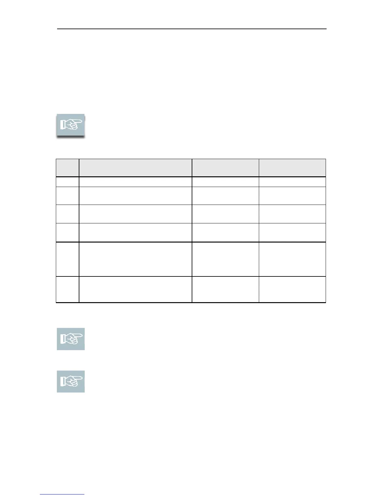
Connect network
The cable pairs for Ethernet RD and TD should remain drilled if
possible up to the connecting terminal on the DOM device.
Ethernet standard
EIA/TIA-T568A
Ethernet standard
EIA/TIA-T568B
Wire 7
(white/brown)
+
Wire 8 (brown)
Wire 7
(white/brown)
+
Wire 8 (brown)
Wire 4 (blue)
+
Wire 5 (white/blue)
Wire 4 (blue)
+
Wire 5 (white/blue)
Data transmission always takes place at terminals 11 to 14.
Please note! If you use PoE via a "mid-span device" (PoE injector),
strands 7 and 8 of the Ethernet cable must be additionally connected to
terminal 9 of the DOM devices and strands 4 and 5 of the Ethernet cable
to terminal 10.
Please note! If a PoE "end-span device" (PoE switch) is used, power is
fed through the data lines in addition to data transmission at terminals 11
to 14 (strands 1, 2, 3, 6). The 9 is no longer needed in this case.
However, you can still connect wires 4, 5, 7 and 8 for insulation to
terminals 9 and 10 if they are not otherwise used in your network cabling.