Preparation EnviroComfort Installation Manual
4 L-2657 ENGLISH
GRILLES AND DUCTING
• Supply-air grille mounted as high as possible.
• Return-air grille mounted as low and as close to the unit as possible.
• Return-air grille mounted away from exhaust and bilge vapors.
• Ducting is pulled taut, straight and properly connected with no excess.
ELECTRICAL
• If pump wires need to be extended by butt connections, make sure they are tightly crimped and heat shrunk.
• AC power source installed and grounded/bonded in accordance with ABYC standards.
• Connect control wires to terminal strip with ring terminals.
SEAWATER COOLING SYSTEM
• Speed scoop located as far below the water line and as close to the keel as possible, with the scoop’s strainer facing
the bow. (See section C of Figure 1: Kit Installation Diagram, page 5.)
• Shut-off valve and speed scoop properly sealed and tight.
• Seawater pump at least one foot (305mm) below water line and securely mounted.
• Strainer mounted below pump with access to filter.
• Double/reversed stainless steel hose clamps on all hose connections.
• Teflon tape on all threaded connections.
• Hose runs uphill from speed scoop to strainer, pump and air conditioning unit.
• Water flowing freely and steadily from overboard discharge while pump is running.
PREPARATION
PLACEMENT OF SYSTEM
Selecting a good location for your air conditioner is the most important part of your preparation. Be sure to consider the size of
the area you are cooling, the air distribution needs, and the size of the unit you have chosen.
Install the unit as low as possible (such as under a V-berth, dinette seat or in the bottom of a locker) and duct the supply air as
high as possible to create an ideal air-flow condition. This type of installation prevents short or premature cycling.
Position the unit on a firm, level, horizontal surface and run the condensate drain line downward from the unit to a suitable drain
location.
Plan all connections, including ducting, condensate drain, seawater in and out, electrical power connections, location of control,
and seawater pump placement, to assure easy access for routing and servicing.
If your kit is supplied with a filtered return-air grille, the filter attached to the unit’s evaporator must be removed. Two filters are
not better than one, as the reduced air flow will decrease performance and possibly freeze the evaporator coil.
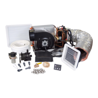
See Figure 1: Kit Installation Diagram, page 5 for an overview of the entire installation and Table 1: List of Parts Referenced in
Kit Installation Diagram, page 6.
WARNING
Never install your air conditioner in the bilge or engine room areas. Ensure that the selected location is sealed from
direct access to bilge and/or engine room vapors.
Do not terminate condensate drain line within three feet of any outlet of engine or generator exhaust systems, nor in a
compartment housing an engine or generator, nor in a bilge, unless the drain is connected properly to a sealed
condensate or shower sump pump.
Failure to comply may allow bilge or engine room vapors to mix with the air conditioner’s return air and contaminate
living areas which may result in injury or death.
 Loading...