Preparation EnviroComfort Installation Manual
6 L-2657 ENGLISH
Installation Notes
Duct Kit Installation
1. Do not install air conditioner in bilge or engine room areas. Do not terminate condensate drain line in bilge or any area
that may be exposed to engine or generator exhaust fumes.
2. Install return-air grill low and supply-air grille high; supply-air grille should not blow toward return-air grille.
3. Install ducting as smooth and taut as possible, trim any excess, avoid any unnecessary bends or loops.
Seawater Kit Installation
Refer to Figure 8: Seawater Pump & Plumbing Diagrams, page 15.
1. Seawater system must have a steady upward flow from inlet to air conditioner, as shown in Figure 8, page 15.
2. Hoses must not have kinks, loops, or high spots where air can be trapped.
3. Pump and strainer must be below water line.
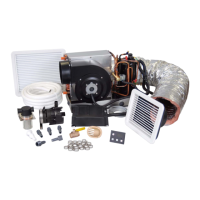
Table 1: List of Parts Referenced in Kit Installation Diagram
L
EGEND AMOUNT DESCRIPTION
A 12.5’ (3.8m) Insulated Ducting
B 1 Supply-Air Grille (the smaller grille in kit)
C 1 Return-Air Grille, filtered (the larger grille in kit)
D 4 Mounting Bracket (see Figure 3, page 8)
E 1 Thru-Hull, plastic 5/8”
F 25’ (7.62m) Seawater Hose, 5/8”
G 1 Air Conditioning Unit
H 3 Adapter, PVC 1/2” MPT x 1/2” HB
I (Pump
PML 250)
2 Adapter, PVC 1/2” FPT x 1/2” HB
I (Pump
PML 500)
1 Adapter, PVC 1/2” FPT x 1/2” HB
1 Adapter, PVC 3/4” MPT x 1/2” HB
1 Coupling, PVC 3/4” FPT x 3/4” FPT
J 1 Strainer with Bracket (1/2” FPT)
K 1 Hose Barb Drain Kit (see Figure 4, page 9)
L 1 Remote Electrical Box
M 1 Seawater Pump, PML250 (6K-12K units) or PML500 (16K units)
N 17 Hose Clamp
O 1 Ball Valve, bronze 1/2”
P 1 Speed Scoop, bronze 1/2”
Q 1 Digital Control Panel
R 1 Electrical Harness
S 1 Pump Power Harness
 Loading...