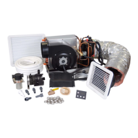
EnviroComfort Installation Manual Preparation
L-2657 ENGLISH 7
4. Speed scoop should be installed as far below the water line and as close to the keel as possible, facing forward.
5. Avoid or minimize 90-degree bends or elbows as much as possible. Rotate pump head toward direction of water flow.
6. Electrical connections for power to unit and pump are to be made by qualified personnel only.
DUCTING ROUTE
Good airflow is critical for the performance of the entire system.
Plan the ducting route to run as straight, smooth, and taut as possible, minimizing the number of 90-degree bends. (Two tight
90-degree bends can reduce airflow by 25 percent.)
SPACING ALLOWANCES & UNIT DIMENSIONS
The following space allowances are suggested minimums. Always allocate enough space for installation and serviceability. See
Table 2: Unit Dimensions, page 7 and Figure 2: Spacing Allowances & Unit Dimensions for Mounting, page 8.
Plan for these space allowances when mounting the unit:
1. Allow a minimum of 6" (152mm) around the perimeter of the unit in the area of the seawater and condensate drain
piping.
2. Allow a minimum of 3" (76mm) of air space in front of the evaporator coil for the return-air intake if it is adjacent to a
bulkhead.
3. Allow a minimum of 3" (76mm) of air space for the electric blower motor ventilation.
4. For flexible ducting connection, allow 2" (51mm) for the duct ring, 1" (25mm) for the duct bend radius, and add
diameter of the ducting to get the total clearance distance (2" [51mm] + 1" [25mm] + duct diameter) as measured from
the blower outlet (this also applies to clearance needed behind the supply-air grille).
NOTE
United States federal law prohibits the intentional release of refrigerant gases into the environment, including the
refrigerant used in this air conditioning system. Special care must be taken when installing, charging and servicing
Dometic equipment to prevent any loss of refrigerant. Dometic does not recommend the practice of using refrigerant
to purge air and moisture from the system at installation. This formerly used practice of purging is in violation of
United States federal law.
Table 2: Unit Dimensions
D
IMENSIONS
UNIT CAPACITIES
6,000 BTU
IN/MM
10,000 BTU
IN/MM
12,000 BTU
IN/MM
16,000 BTU
IN/MM
A - Duct Size 4.0/102 6.0/153 6.0/153 6.0/153
B - Base Depth 8.0/204 8.75/223 8.75/223 10.25/261
C - Overall Depth 9.0/229 9.63/245 9.63/245 11.25/286
D - Width 16.0/407 22.0/559 22.0/559 22.0/559
E - Height 11.25/286 13.50/343 13.50/343 13.5/343

 Loading...