INSTALLATION PROCEDURES Eskimo Ice Installation & Operation Manual
8 L-3040 ENGLISH
6. The EI540D now REQUIRES a Constant Torque Hose Clamp to secure the ice delivery hose to the auger spout.
It is supplied with the machine and attached to the Auger spout with a black wire tie. The clamp must be
installed behind the 8 protruding dimples on the auger ice spout. The use of another type of clamp will void
the warranty and liability of ice overflow and damage if the hose comes off while producing ice. Secure hose
end with constant torque hose clamp to auger spout.
It is CRITICAL that you check the integrity of this hose connection when you perform the system start-up test.
(See “Mandatory System Start-Up Test” on page 13.)
7. Securely strap hose to bulkhead every 12” (30.5cm), keeping in mind that the hose will be much heavier once filled
with ice. Be careful not to kink, flatten, oval or crush hose, because any obstructions will prevent free flow of ice.
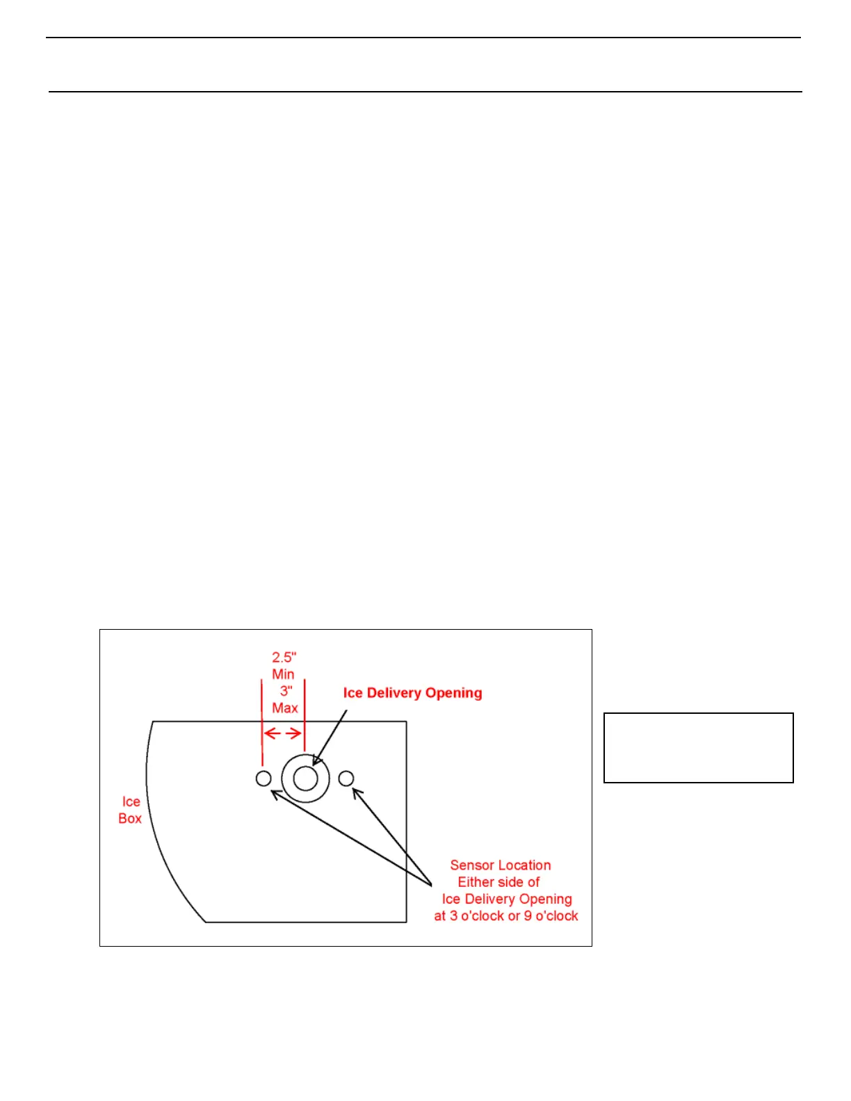
INSTALLING THE ICE-LEVEL SENSOR
To prevent overflow, this sensor stops ice production when the ice in the storage box reaches the level of the sensor. Use
Figure 6 below to determine placement for the ice-level sensor at the storage box location. The EI540D will not operate without
the ice-level photo sensor installed.
Test the photo sensor for correct operation to avoid machine damage and avoid ice overflow. See “Mandatory System Start-Up
Test” on page 13.
1. The sensor must be located 2.5” (64mm) minimum to 3” (76mm) maximum to the left or right side of the ice-delivery
hole. Drill a 23/32" (19mm) hole for sensor.
2. Use the 2 lock nuts provided to secure sensor into the hole.
3. Use marine-grade sealant around the hole if desired. (Remember that the unit may have to be removed at some time.)
4. Route the cable to the ice maker’s electrical box and plug the end into the ice-bin sensor socket. See the appropriate
electrical wiring diagram in this manual for the voltage model you are using.
NOTE wiring changes from earlier Eskimo Ice models: The wiring has changed in the electrical box for the ice
sensor. There are 4 wires in the sensor harness: white, black, blue and brown. The signal wire in the center position of
the ice-level sensor plug is now a white wire, not black as before. The white wire was previously cut off at the grey
insulation. Now the black is cut off and the white is used. Note the photo sensor can be used for old as well as new. It
is just dependent how it is wired.
Figure 6: Location of Ice-Level Sensor (front view)
INSTALLING THE FEEDWATER SYSTEM
Feedwater for the unit should be fresh water supplied by the boat’s potable water system. The water reservoir has a float switch
to ensure the unit does not operate without a water supply.
Mount the ice-delivery
hose as high as possible
in the ice-storage box.