Eskimo Ice Installation & Operation Manual INSTALLATION PROCEDURES
L-3040 ENGLISH 13
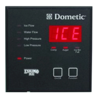
INSTALLING THE REMOTE DIGITAL DISPLAY
For easier operation accessibility, an optional remote digital display may be installed wherever desired, however, it can not be
exposed to saltwater spray. The remote display requires a cable that must be ordered separately, and is available in lengths up
to 100’ (30.5m).
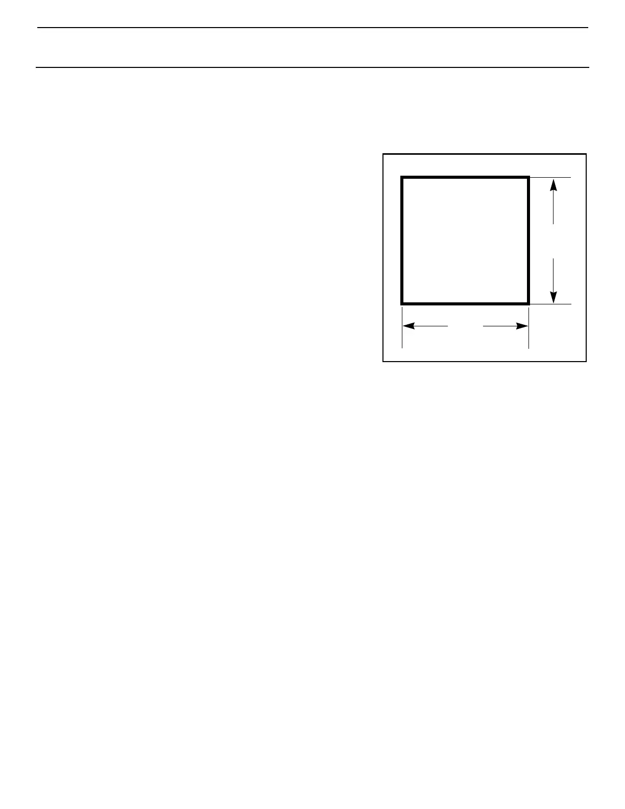
Figure 10: Cutout Dimensions
For Digital Display
1. Find a convenient location that is protected from saltwater spray.
2. Cut out a square hole that is 3-3/16” x 3-3/16” (82 x 82 mm). See
Figure 10 to prepare the mounting space.
3. Route the display’s cable to control box and plug into the mating
8-pin male RJ45 connector.
4. Mount the remote display into the cutout.
5. If you are relocating the existing display, cover the hole on the
back of the box.
MANDATORY SYSTEM START-UP TEST
It is CRITICAL that you test the durability of the hose connections, the ice-
level sensor, and the amp-sensing feature during the installation process:
1. Run the machine to start producing ice. See “OPERATION” on
page 14.
2. Block the output end of the ice delivery hose and run the system
until the machine shuts down with the OCA code to confirm the
overload feature.
3. Check to see that the unit displays the OCA code indicating an
ice-hose clog, restriction, actual auger motor overload, possible
motor problem, or internal gear problem. The amp-sensing
feature of the control monitors the amp draw of the auger unit
and shuts down and locks out when an overload is sensed. The
115V auger locks out at 2.6 amps; the 230V/60Hz and 220V/50Hz augers lock out at 1.3 amps. NOTE: The Spout fault
code of earlier models is no longer used since there is no spout switch on this unit.
NOTE: If an OCA has occurred and you remove the immediate obstruction, such as ice piled up in front of the
discharge, and then reset the unit, a second OCA might occur if a sufficient amount of time has not elapsed to allow ice
to melt in the auger or where ice might be compacted in the hose on a long run.
4. Check the hose connection at the auger end. It is CRITICAL to make sure that the ice delivery hose did not
come off the auger spout or move in any way. If there is a problem, refer to “Installing Ice-Delivery Hose” on
page 7 and make the hose secure then retest.
5. Reset the system and resume ice production to test the photo sensor for correct operation to avoid machine damage
and avoid ice overflow. When ice blocks the sensor the unit should stop producing ice, and this should occur before the
collection bin overflows.
3-3/16”
(82mm)
3-3/16”
(82 mm)
Cutout Dimensions
Note: Image shown is not to scale.