16
EN
Installation Rooop Air Conditioner (Air Distribution Box, Wall Thermostat Controls)
3. Reach up into the return air opening of the rooop
component and pull down the rooop component’s
electrical cord and wiring harness.
4. If the rooop component has a built-in board,
complete the following:
a. Mount the junction box to the framing in front
of the roof opening, using the installer-supplied
screws.
b. Install the strain relief.
8 Installation
WARNING: FIRE OR ELECTRICAL SHOCK
HAZARD. Failure to obey these warnings
could result in death or serious injury.
• Shut off the gas supply, disconnect the 115 VAC
power from the RV, and disconnect the positive
(+)12VDC terminal from the supply battery before
drilling or cutting into the RV.
• Provide grounding in compliance with all applicable
electrical codes.
This section describes how to install and mount the wall
thermostat and optional sensor.
8.1 Installing and wiring the
thermostat and optional sensor
To install the wall thermostat, choose one of the
following options based on the type of wiring.
• “Using RJ-45 Wire to Supply Communication to the
Thermostat” on page16, or
• “Using RV-C BUS and Multiplexer to Supply CAN
Communication to the AC” on page17.
8.1.1 Using RJ-45 Wire to Supply
Communication to the Thermostat
I
If installing non twisted pair cable, go to “Using
RV-C BUS and Multiplexer to Supply CAN
Communication to the AC” on page17.
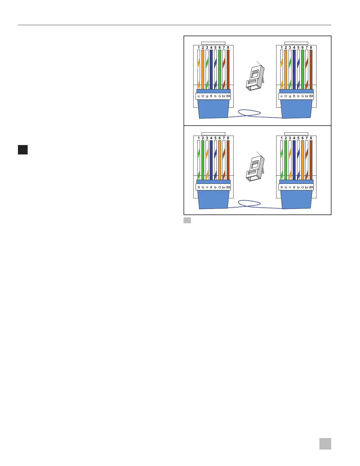
T-568B T-568B
T-568A T-568A
qq
qq
T-568B T-568B
T-568A T-568A
13 Connecting the RJ-45 plugs to the communication cable(s)
q
Pin 1
1. Terminate the previously run 8-conductor
communication cable with two RJ-45 plugs
using a crimping tool. Refer to the crimping tool
manufacturer for instructions. See “Routing the
thermostat communication cable” on page13.
I
The pins of both RJ-45 plugs must match: pin1
must connect to pin1 on the other connector, pin2
must connect to pin2 on the other connector, and
continuing for all remaining pins. Pins 3 and 6 must be
twisted at minimum rate of 25 twists per 39in.(1m).

 Loading...