19
EN
Rooop Air Conditioner (Air Distribution Box, Wall Thermostat Controls) Installation
8.3.1 Locating the DIP switches
qq
ww
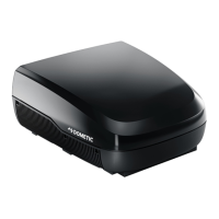
18 Electronic control box DIP switch location
q
DIP switch
w
Electronic control box
The electronic control box is located at the return air
opening on the base of the AC and the DIP switches are
visible through the opening.
The DIP switches are set to the Off position (except for
the 120 ohm switch) when shipped from the factory.
Heat pump models will have the appropriate switch
selected in the On position. Placing the switch in the On
position selects that option.
8.3.2 Setting the DIP switches
This section describes the appropriate electronic
control box DIP switch settings. The position should be
set to the appropriate On or Off position based on the
equipment options installed by the RV manufacturer.
ww
qq
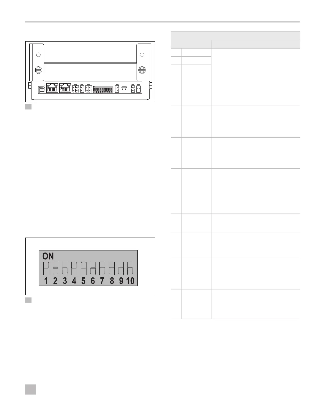
19 DIP switch board
q
On or closed switch position
w
Off or open switch position
If your RV has more than one electronic control box
installed, configure each electronic control box with the
appropriate DIP switch settings.
If necessary, press each switch On (Closed) or Off (Open)
according to the following configuration table.
DIP switch setting configuration
DIP location Description
1 Zone 2
Each thermostat can have up to four
zones. If only one rooop component is
installed, it becomes zone 1 by default
and DIP switch settings for zones 2, 3, or
4 are not required.
If more than one rooop component is
installed, assign each rooop component
a separate zone (2 through4). Each
rooop component must have a different
zone setting.
2 Zone 3
3 Zone 4
4 Stage
For applications requiring two
rooop components to work together in
the same zone, set the Stage DIP switch
to the On position.
Otherwise, leave in the Off position.
5 Furnace
1
If a Furnace/Hydronic heating
system has been connected to this
rooop component, set the Furnace DIP
switch to the On position.
Otherwise, leave in the Off position.
6 Gen Start
1
To configure the Automatic Generator
Start for a new installation, refer to
“Routing an automatic generator start
(AGS) feature via RV-C (optional)” on
page15. Leave this DIP switch in
the Off position, unless it is required for
backwards compatibility using the CMC
protocol.
7 Heat Strip
1
Leave this DIP switch in the Off position,
unless it is required for backwards
compatibility using the CMC protocol.
8 Heat Pump
For Heat Pump models, this DIP switch is
set in the On position from the factory.
For non-Heat Pump models, change this
DIP switch to the Off position.
9 Dehumidify
1
The Dehumidify is not used on this
rooop component.
Leave this DIP switch in the Off position,
unless it is required for backwards
compatibility using CMC protocol.
10 120 ohm
CAN
termination
resistor
This DIP switch is in the On position from
the factory to enable RV-C (CAN BUS)
communication. Only the first and last
devices on the CAN bus should enable
the 120 ohm termination resistor.
1
Climate Module Communication (CMC) only
 Loading...