34
Dometic
®
MANUAL
Refrigerators
10C. RELAY (RM2604/RM2610/RM2804RM2810
3-WAY MODELS ONLY)
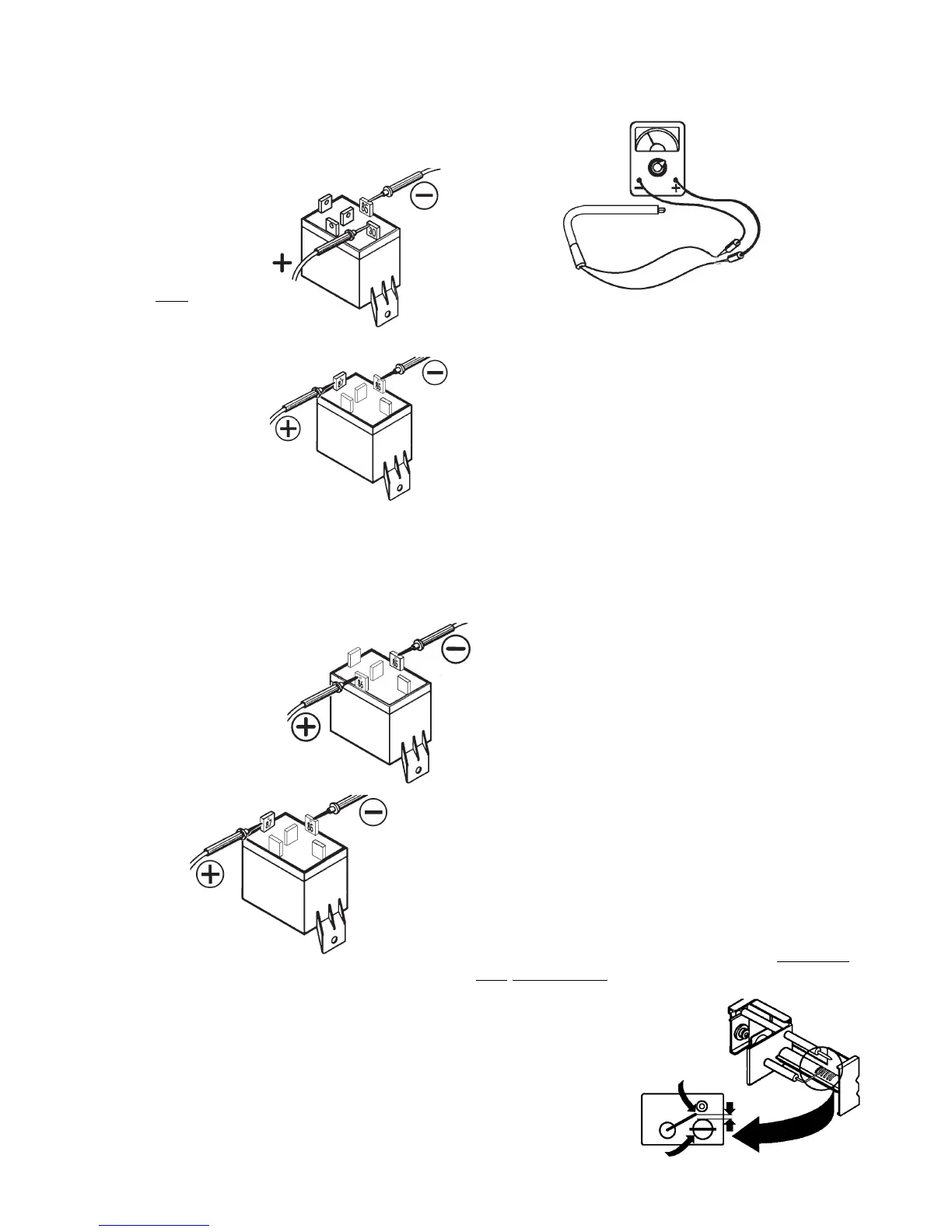
The relay controls the circuit to the DC
heating element. The load (amps)
of the DC heating element goes
through the relay.
To check the relay, first
verify the selector switch is
on DC mode and the
thermostat) is NOT complet-
ing the circuit. Next, verify
voltage is present between
terminals 85 and 30. If
voltage is not present,
check wiring to both
terminals.
Next, check for voltage
between terminals 85 and
87. If voltage is present,
the relay is defective and needs
to be replaced.
Second, verify the selector switch is on DC mode and
the thermostat ) is completing the circuit.
Next, verify voltage is present between termi-
nals 85 and 86. If no voltage is
present, check wiring and
connections.
Next, if voltage is present,
between 85 and 86 terminals,
then voltage should be present
between terminals 85 and 87. If
no voltage is present, the relay is
defective, replace it.
For values, refer to Technical Data Section, Pg. 86.
85
30
87
85
85
86
87
85
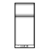
11C. HEATING ELEMENT
(3-WAY MODELS ONLY)
The heating element is designed to deliver a predeter-
mined amount of heat to the cooling unit. Check the
heating element with ohms resistance using a properly
calibrated ohm meter. This check is to be done with the
element at room temperature.
12C. IGNITER
1. MODEL RM2310, 2410, 2452, 2453
The piezo lighter is a self-contained assembly which
generally does not need maintenance. When the button
is pushed, a spring loaded striker creates a spark. If
there is no resistance when pressing the button, the
piezo igniter is defective and must be replaced. If the
piezo snaps or has resistance when the button is
pushed, but there is no spark, the problem lies in the
electrode or electrode wire.
2. MODEL RM2510, 2610, 2810, 2552, 2553
The igniter is an electronic device that produces high
voltage to create a spark at the burner, only on gas
mode. First, check that the switch is in the gas mode
and is completing the circuit. Next, verify proper voltage
at the positive (+) and ground (-) terminals of the igniter.
The reading should be within one volt of incoming
voltage at the terminal block. A voltage drop of more
than one volt would indicate a loose connection. No
voltage would indicate an open circuit, check switch,
wiring and DC voltage requirements.
ELECTRODE
To check the electrode, first do a visual inspection for
cracks or breaks on the ceramic insulator. Also, verify
the mounting bracket is attached properly to the elec-
trode. If either of the above conditions are found, replace
the electrode. Next, check the spark gap. It must be set
at three sixteenths (3/16) of an inch and the tip of
electrode above the slots in the burner.
NOTE: If igniter and high voltage cableare good and
there is no spark at the tip of the electrode, REPLACE
THE ELECTRODE.
3/16"
ELECTRODE
TIP
BURNER