Dometic
®
MANUAL
Refrigerators
47
The input battery voltage must rise above 12.8 volts for
25 minutes before DC operation can resume.
As soon as the input voltage rises above the required
12.8 volts, the DC mode lamp (F) will illuminate. How-
ever the control system will remain in the 25 minute DC
delay mode and operate on gas. This delay is to allow
sufficient time for the vehicle charging system to re-
charge the battery. If 120 volt AC becomes available
during the 25 minute delay, the control will automatically
switch to the AC energy source.
STANDBY MODE OF OPERATION
This control system contains a feature where it will
continue to operate the cooling system in the event of a
failure of a major operating component. Two different
modes of operation can occur in this category.
If for some reason the display module becomes non-
functional, the control system will revert to fully auto-
matic operation - selecting the best energy source
available with AC and GAS priority. The temperature of
the refrigerator will be maintained at the MID position
within normal temperature tolerances. The power mod-
ule will continually attempt to reestablish operation of
the display module.
The second standby mode of operation will execute
when a failure of the temperature sensing device or
associated electronic circuitry occurs. If this should
occur, the control system will operate on the energy
source selected via the control panel. The cooling unit
will run continuously on the selected energy source. The
refrigerator will continue to operate in this mode indefi-
nitely or until a new sensor is installed and the system
is reset.
6D. AC VOLTAGE REQUIREMENTS
The refrigerator is a 120 volt AC, 60 Hz appliance. The
proper operating range is 100 to 132 volts. Check the
AC volts at the receptacle where the refrigerator is
attached. If voltage is outside of the proper operating
range, correct the power source problem.
If voltage drops below 100 volts, cooling efficiency will
decrease with voltage decrease. The refrigerator will not
switch to another mode of operation until all AC power
is lost.
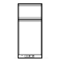
7D. AC COMPONENTS-
HEATING ELEMENT
The heating element is designed
to deliver a predetermined
amount of heat to the cooling
unit. To check a heating
element, remove the heater
leads from the lower circuit
board and measure for
proper resistance across the
two leads with a properly
calibrated ohm meter. This
check is to be done with the
heating element at room
temperature.
For values, refer to the TECHNICAL DATA SECTION.
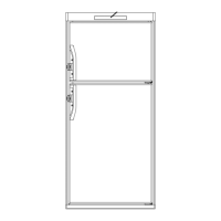
8D. DC COMPONENTS
HEATING ELEMENT
The heating element is designed
to deliver a predetermined amount
of heat to the cooling unit. Check
the heating element with ohms
resistance using a properly
calibrated ohm meter. This
check is to be done with the
element at room tempera-
ture.
For Values, refer to Technical Data Section Pg. 86.