52
Dometic
®
MANUAL
Refrigerators
manually. For AUTO step sequence, press the
AUTO/GAS Mode Selector Switch to the DOWN
position. The AUTO Mode Indicator will illuminate.
If each lamp illuminates during the check, the display
circuit board is good.
In automatic test mode, each load is activated for
approximately four (4) seconds then released.
The control system will automatically exit the
diagnostic sequence in approximately four (4)
minutes or when power is turned OFF.
The Temperature Indicator Lamps are used to
indicate which part of the control system is being
tested. When position #1 is illuminated, the
control is in an idle position with all output loads
off. To activate the first load simply push the
Temperature Selector Switch.
All of the checks listed below are done on the lower
circuit board.
The manual test sequence is as follows:
Position #1: Idle Position, all loads off.
Position #2: Activate AC Heater. Check for AC volts
at terminals J7 and J8.
Position #3: Activate Gas Solenoid. Check for DC
volts at Gas Solenoid white wire (-) and
yellow wire (+).
Position #4: Activate DC heater. Check for DC volts
between J1 (+) and J10 (—).
Position #5: Activate spark ignition system. Check for
DC volts to (+) terminal of igniter and
ground.
If you experience a problem on any of the above
checks, verify the fuses on the lower circuit board
are good.
If all checks prove to be good, and the refrigera-
tor does not operate on electric mode, replace
the lower circuit board. It has been damaged by
AC volts in excess of 180 volts.
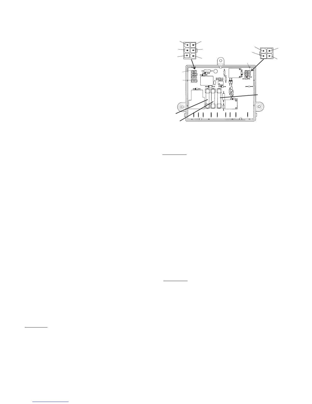
LOWER CIRCUIT BOARD
NOTE: The PAL tester will allow for proper testing of the
integrity of the upper and lower circuit boards. PAL is
available from your Dometic parts distributor.
P1
P2
P3
J1 J2 J3 J4 J5 J6 J7 J8 J10
35 AMP
FUSE
3 AMP FUSE
FIVE
AMP
FUSE
3
2
1
6
5
4
3
4
1
1
22
A. DC VOLT: ALL TESTS ARE TO BE DONE WITH
THE REFRIGERATOR IN THE COOLING MODE.
Before any checks are made, make sure the board is
receiving proper DC volts (see Sec. 4). Measure volts
between terminal J4 and the ground strip. Voltage
should be the same as at the positive (+) and nega-
tive (-) on the terminal block. If not, check for loose
connections.
B. AC MODE: NOTE: The PAL tester will allow for
proper testing of the integrity of the upper and lower
circuit boards. PAL is available from your Dometic
parts distributor.
ALL TESTS ARE TO BE DONE WITH THE RE-
FRIGERATOR IN THE COOLING MODE.
For AC heating element operation, check that
incoming AC voltage is present at terminals J5 and
J6 on the circuit board. If voltage is below 100 volts.
Check for voltage at the heating element connection
terminals J7 and J8 on the circuit board. If no voltage
is present, check the 5 amp AC and 3 amp DC fuses.
If fuse is defective, replace the fuse. If fuses are
good, replace the circuit board.
NOTE: Before installing a new circuit board, deter-
mine and correct the cause of the failure. If voltage is
present, do not change the circuit board. Check the
AC heating element.
C. DC MODE: NOTE: The PAL tester will allow for
proper testing of the integrity of the upper and lower
circuit boards. PAL is available from your Dometic
parts distributor.
ALL TESTS ARE TO BE DONE WITH THE RE-
FRIGERATOR IN THE COOLING MODE.
For DC heating element operation (on 3-way models
only), check for voltage between terminal J4 on the
circuit board and the ground strip. If voltage is 12.8
volts DC or above, check for DC volts between the
heating element (J1) connection and the ground strip.
If there is no voltage present, check the fuses and
the DC heating element. If these check good, change
the circuit board.
NOTE: If DC volts are below 12.8V DC, see "Opera-
tion".