60
Dometic
®
MANUAL
Refrigerators
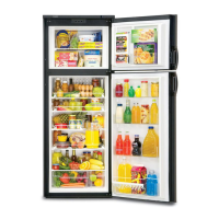
With main ON/OFF switch on display panel in OFF
position:
Check for DC voltage at Plug 1, Terminal 4 (orange
wire) and terminal 5 (red wire) negative (–) DC on the
lower circuit board. If no voltage, then check fuse
condition. Replace if blown. Check for DC voltage
between J4 and J10 terminals on the lower circuit board.
If fuse is good and there is battery voltage at J4, remove
and replace lower circuit board.
Next, check for DC voltage at the upper circuit board
between terminal 4 (orange wire) and terminal 3 (red
wire) which is negative (–) DC. If no voltage, and your
previous check proved voltage at the lower circuit board
between these wires, replace the cable assembly. If DC
volts are present, proceed to the next check.
With main ON/OFF switch on display panel in ON
position:
Check for DC volts between terminal 3, red wire (–)
negative and terminal 5 (green wire) and terminal 1
(black wire). If there is no voltage, the ON/OFF
switch on upper circuit board is defective. Replace
the upper circuit board. If voltage is present, the ON/
OFF switch is good.
Next, do the same voltage test at the lower circuit
board. Red wire (–) negative plug 1, terminal 5, to
green wire, plug 1, terminal 1 and black wire, plug 1,
terminal 3. If there is no voltage and you had voltage
on previous test, the cable assembly is defective and
you must replace it. If voltage is present, the ON/
OFF switch on the upper circuit board and cable
assembly is good.
LOWER CIRCUIT BOARD
NOTE: The PAL tester will allow for proper testing of the
integrity of the upper and lower circuit boards. PAL is
available from your Dometic parts distributor.
The controls for Models RM2612, RM2812, RM2652 and
RM2852 are unique to these models. They are NOT
interchangeable with any other models.
On Model RM2612, below Serial Number 41900000,
there were three separate and distinct versions of
controls as described below. The various components
MUST NOT be mixed.
If you suspect mismatched part numbers, compare the
part numbers on parts to the ones listed below to ensure
a proper match.
The RM2612 with Serial Number 41900000 or higher
will have Version III controls as original equipment.
The RM2812, RM2652 and RM2852 should have only
Version III controls as original equipment.
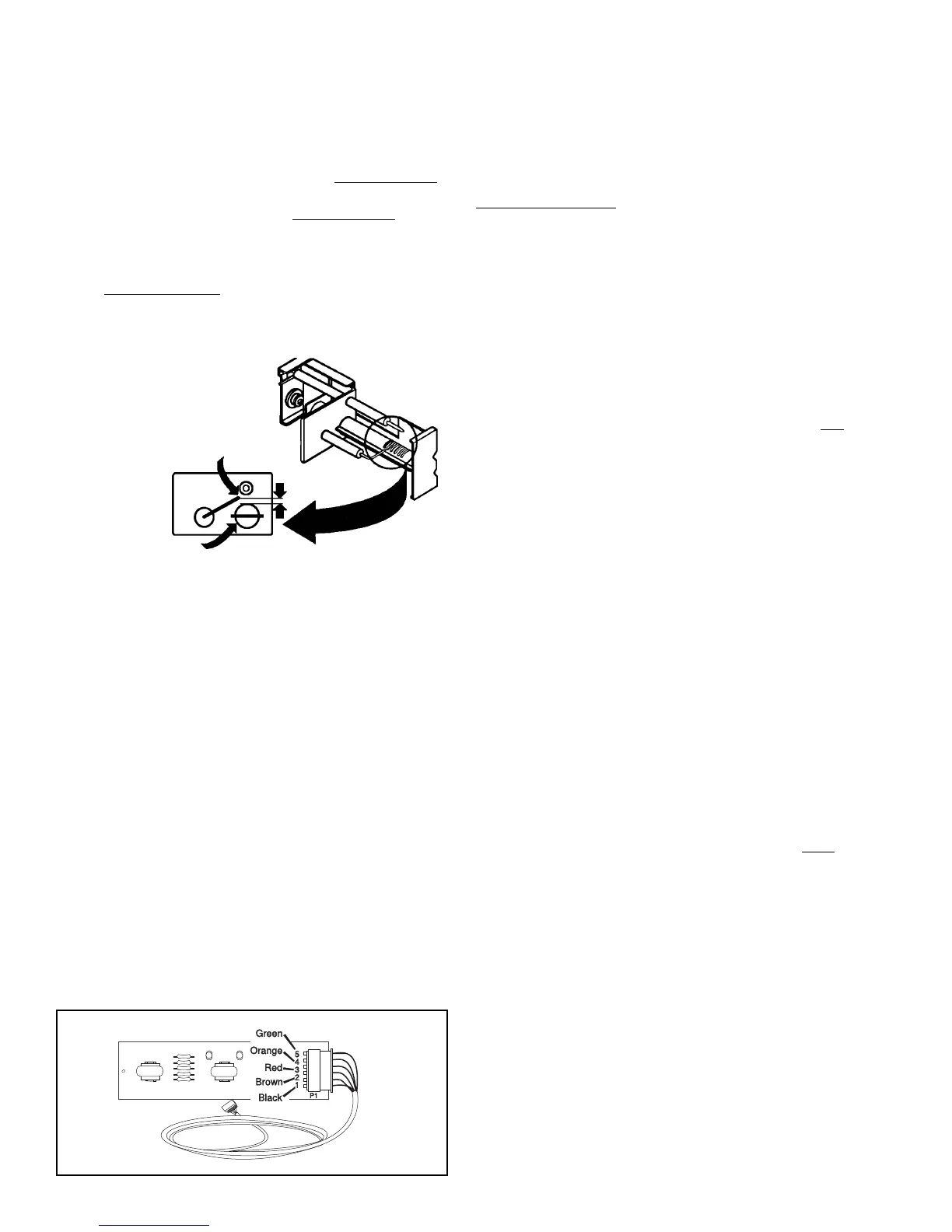
ELECTRODE
TIP
3/16"
BURNER
HIGH VOLTAGE CABLE
Disconnect DC power at the refrigerator terminal block.
Disconnect high voltage cable from electrode. Recon-
nect DC power. If sparking starts during trial-for-ignition
(approximately 45 seconds), the cable is good.
If there is no sparking during trial-for-ignition
(approximately 45 seconds), disconnect DC power and
disconnect high voltage cable at the igniter. Reconnect
DC power. If there is a sparking sound from the igniter
during trial-for-ignition
(approximately 45 seconds),
then replace high voltage cable.
ELECTRODE
First, do a visual check for
cracks or breaks on the
ceramic insulator. Verify
the mounting bracket
isattached
properly to the
electrode. If
either of
the above
is found,
replace the
electrode.
The spark gap must be set at three sixteenths (3/16") of
an inch and tip of electrode above the slots in the
burner.
If igniter and high voltage cable
are good and there is no spark at the tip of the
electrode, replace the electrode.
THERMOCOUPLE
The thermocouple is a component extending above the
burner assembly so the tip is in the path of the flame.
During normal gas operation, the thermocouple should
produce 25 to 35 millivolts when connected to the lower
circuit board. Any reading below 18 millivolts could
cause erratic gas operation. NOTE: A reading of 18 or
less could be caused by low gas pressure or improper
thermocouple location.
UPPER CIRCUIT BOARD
NOTE: The PAL tester will allow for proper testing of the
integrity of the upper and lower circuit boards. PAL is
available from your Dometic parts distributor.