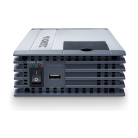
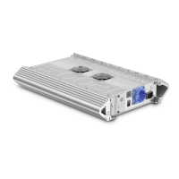
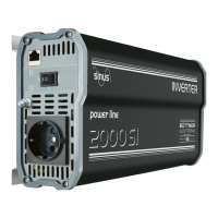
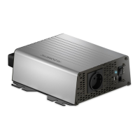
Connecting the inverter SinePower
16
9.5 Connecting external switch to turn device on and off
I
You can use the following as an external switch:
• External switch, voltage supply from the inverter: fig. 0 A
• Control unit with relay or transistor circuit (TR): fig. 0 B
• External switch with voltage supply from the battery (BAT) of the vehicle:
fig. 0 C
• External switch with its own voltage supply (DC POWER) e.g. from the ignition:
fig. 0 D
➤ Set the main switch (fig. 2 1) to “OFF”.
➤ Make sure that the connection for the remote control (fig. 2 11) is not assigned.
➤ Set the main switch (fig. 2 1) to “REMO.”.
➤ Connect the external on/off switch with the connection cable to the terminal
(fig. 2 12).
9.6 Connecting the fault display relay
You can install a relay which monitors whether the 230 V input is connected.
Thereby you can, for example, implement an immobiliser so that the vehicle cannot
be started when the 230 V input is connected.
➤ Connect the relay as shown (fig. a):
– NO: normally open contact
– COM: common contact
– NC: normally closed contact
Relay specification:
NOTE
Use cables with a cable cross section of 0.25 – 0.75 mm².
Maximum voltage Load
Current consumption
NO NC
250 Vw Ohmic 0.5 A 0.5 A
12 V/24 Vg Ohmic 1 A 1 A
DSP1300T-3500T--IO-16s.book Seite 16 Freitag, 1. Dezember 2017 8:54 08
 Loading...
