10
EN
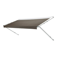
Installation Slide Topper
I
Unfurling the awning fabric more than one
revolution of fabric can cause issues with the awing
function.
9. With the slide-out room of the RV completely closed,
carefully li the Slide Topper to the installed awning
rail end above the top of the slide-out.
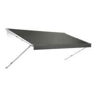
10. While one person guides the awning fabric (or
awning roller cover, if applicable) into the awning rail,
carefully slide the Slide Topper until the fabric is in the
desired position.
I
A stepladder may be necessary to guide the fabric.
4.2 Installing the Mounting Brackets
1. Drill a 3/16 in. (0.12 cm) [7/32 in. (0.56 cm) if you are
drilling into steel] hole approximately 1 in.
(2.5 cm) deep into the slide-out room on the marked
hole locations.
2. Apply sealant to the provided #10 - 12 x 1 in. screws.
3. Place the mounting brackets onto the marked
locations on the RV slide-out room.
4. Tighten the screws through the mounting bracket and
into the solid structure of the RV slide-out room.
I
If an optional spacer kit is needed, use the #10 x
1.75 in. screws provided with the kit. Use the 3/16
x 1 in. oscar rivets when installing the mounting
brackets onto laminated walls.
q
r
w
y
e
t
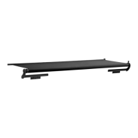
10 Securing the Mounting Bracket
q
Mounting Bracket
r
Extension Cap
w
#10 - 12 x 1 in. Screw
t
LH Arm
e
Extension
y
Slide-Out Room
5. Repeat steps 1 – 5 for the other mounting bracket.
Do not allow the mounting brackets to extend more
than half their length beyond the end of the extension
bar. At least 50% of the mounting bracket length must
be inserted into the extension.
6. Center the Slide Topper on the RV slide-out room.
w
r
q
e
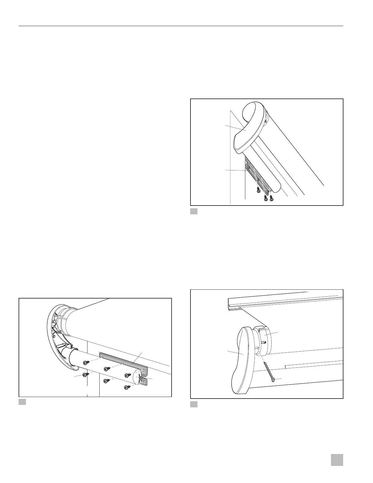
11 Securing the Extension to the Mounting Bracket
q
Mounting Bracket
e
LH Arm
w
#8 – 18 x 3/8 in. Screw
r
Extension
7. Insert the provided #8 – 18 x 3/8 in. screws into the
mounting brackets.
8. Clamp the Slide Topper extensions onto the
mounting brackets.
w
e
q
12 Removing the Cotter Pin
q
Cotter Pin
e
LH Arm
w
End Cap