6
EN
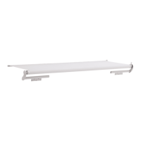
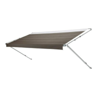
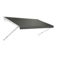
Pre-Installation Slide Topper
t
o
a
q
w
t
y
u
i
e
r
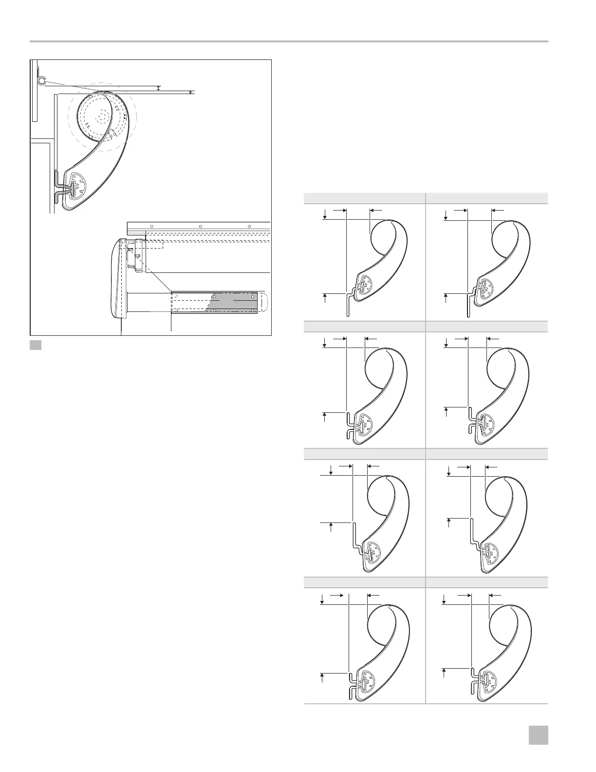
3 Short Mounting Bracket Clearance
q
0.5 in. (1.3 cm) min. –
4 in. (10 cm) max.
y
Slide-Out Room Flange
w
0.25 in. (0.6 cm) min.
u
Extension
e
Mounting Bracket
i
Mounting Bracket
r
Slide-Out Room
Flange
o
Rotating Assembly
t
Awning Rail
a
0.5 in. (1.3 cm) min.
* Callout 10 represents the minimum clearance required
between the Slide Topper rotating assembly, all
obstructions on the RV slide-out room, and all
obstructions on the stationary wall.
Confirm the identified clearances. In addition, the
Slide Topper must have a 0.5 in. (1.3 cm) minimum
clearance between the Slide Topper rotating assembly,
all obstructions on the RV slide-out room, and all
obstructions on the stationary wall. Optional bracket
spacers may be used to achieve this clearance.
3.3 Identifying the Bracket
Configuration
Use this section to identify the Slide Topper
configuration of your application.
I
If the slide-out room of the RV has extra large
flanges, mount the brackets directly onto the flange
only if it provides a solid structural support. Never
mount brackets on an unsupported area of the
flange or on the awning rail.
A B
Y
Y
C D
Y
Y
E F
Y
X
Y
G H
Y
Y